Wiring harness design in CATIA V5 - 3D modeling Week 2 Challlenge
To define the connectors as an Electrical connectors
Defining the parts as an electrical connectors or clips we need electrical part design work bench. In electrical workbench there is an option to define and connector as an electrical connector the image of that option is shown below

Define connector
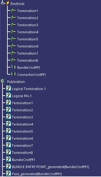
After selecting the above option one dialogue box will open in which we can edit the name of the connector and we need to define the poles of connector, after that in tree struture it ll be automatically shown as snown in the image below
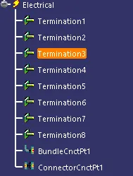
In the above image Termination 1 to 8 are the poles, which define it as 8 pole connector.
Now after defining the connector as an electrical part we need to define the bundle entry point with the option shown in the image below

Define bundle connection point
After selecting the bundle connection point one dialogue will open in which the name of the bundle is given by default we can change as per our prefence after that in representation we need to select the face of the bundle entry, now the point of the bundle entry is need to be selected, After that in intial condition we need to select the face which is normal to the entry.
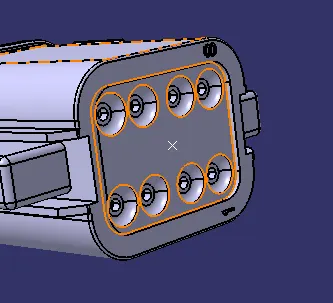

In tree structure
Now time to define the connector connection point with the icon shown in the image below

Define Connector Connection point
It is also same as the bundle entry point in which firest option is to change the name of the connector connection point after that in representation point is need to be selected and in contact face of the connector in which mating is going to happen, coincidence will be Y axis and Orientation will be X axis
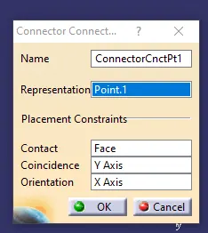

Y axis should be in the mating direction
X axis should be in the Locking direction of the connector.
And the last is Cavity connection point the icon is shown in the image below

Define cavity connection point
It is also same as the connector connection point in which firest option is to change the name of the Cavity connection point after that in representation point is need to be selected and in contact face of the rib in which mating is going to happen, coincidence will be Y axis and Orientation will be X axis
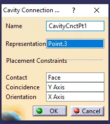

Image of Connector TYCO 174357-2 is shown below
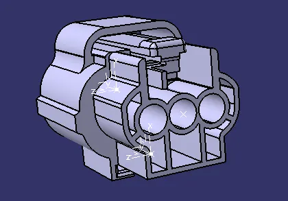
Bundle entry point (3 pole)
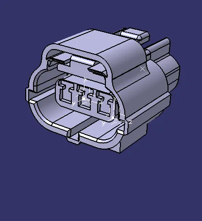
Connector Connection point
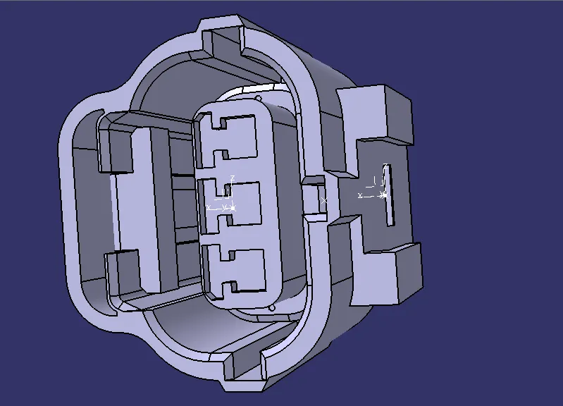
Cavity connection point
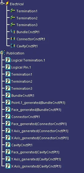
Tree structure
TYCO Cavity 85229-2
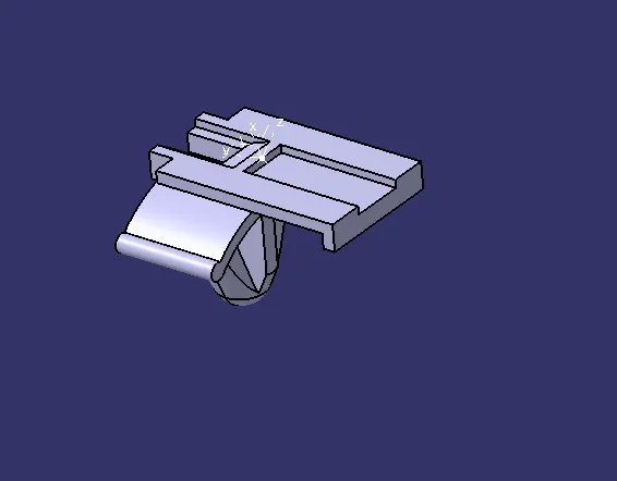
Cavity connection
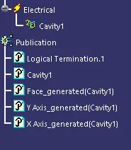
Tree structure
Image of connector DT06-08SA is shown below
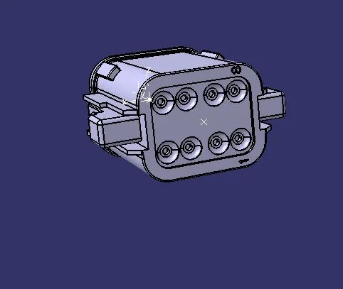
Bundle entry point (8 pole)
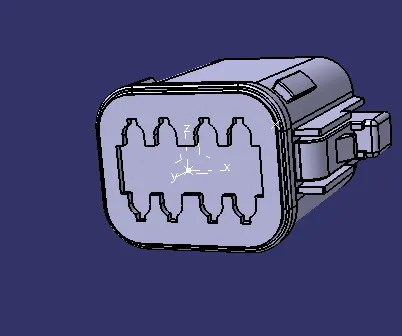
Connector Connection point
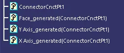
Tree structure