Wiring harness design in CATIA V5 - 3D modeling Week 2 Challlenge
Aim;-To define the all the Mechanical&Electrical components into electrically defined and create a catalouge for the all components.Download following connectors & Connector clip cad data from given link & define it as Electrical Connector using Electrical Part design Workbench. Define all the necessary properties to Connectors & Clip.
- Deutsch DT06 – 08SA ( https://www.te.com/usa-en/product-DT06-08SA.html)
- Tyco 174357-2 (https://www.te.com/usa-en/product-2-174357-2.html?source=header-match)
- Tyco 85229-1 – (https://www.te.com/usa-en/product-85229-1.html?q=85229&source=header)
Indrouction to Wiring Harness
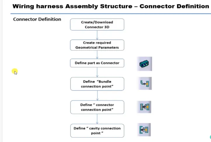
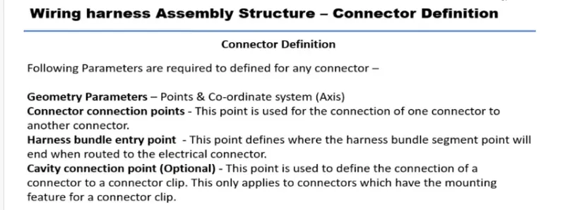
CONNECTOR DEFINITION IN CATIA V5
DUTSCH DTO6-08SA
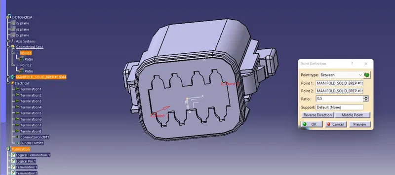
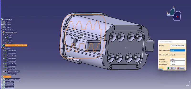
CONNECTOR CONNECTION POINT
create a midpoint of the contact face
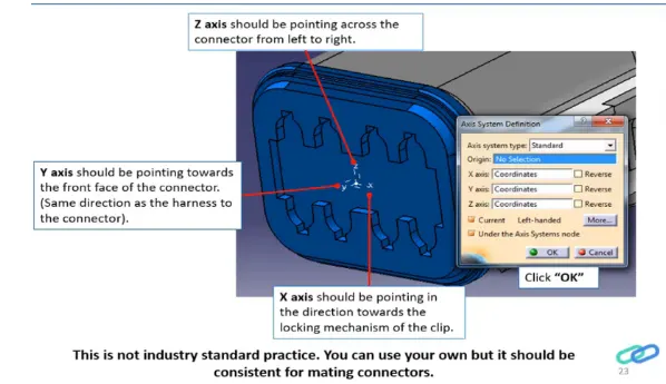
create a axis system with respect to thye midpoint Which have created and defining axis direction as show in below
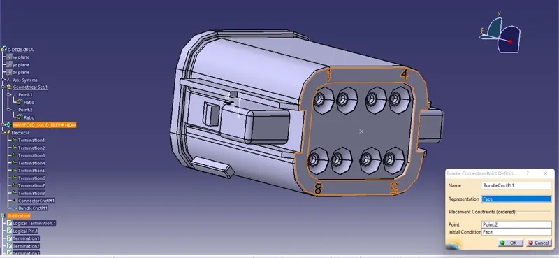
BUNDLE CONNECTION POINT
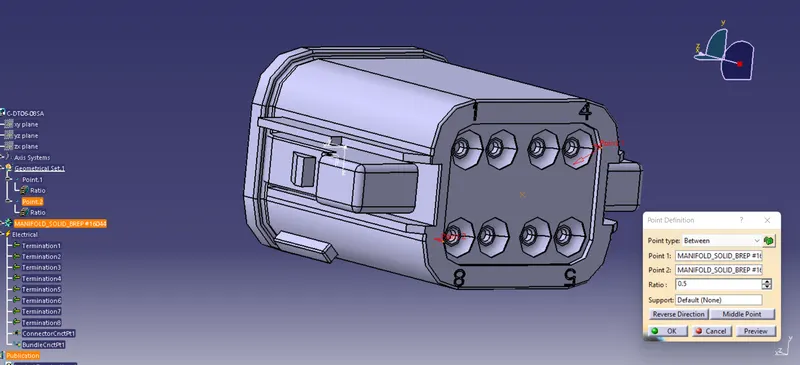
Going to electrical part design work bench convert mechanical part to electrical part.
Define part as connector in catia v5.given the no.of termination 8
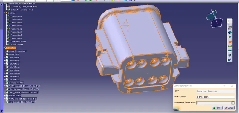
Define the bundle connection point
Define the connector connection point
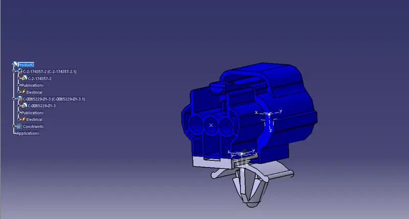
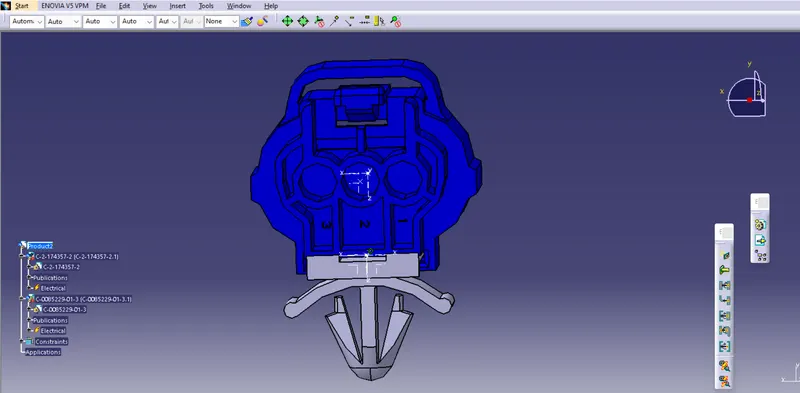
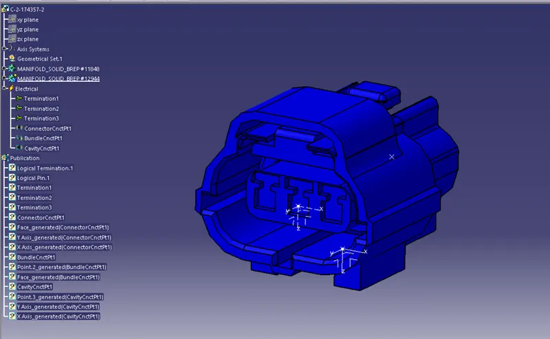
TYCO174357-2
- Create a midpoint
- Create connector connection point
- Create a connector connection axis system
- Create a cavity connection point
- Create a cavity connection axis system
- Switch to the electric part design and define part as a connector
- Define the connector connection point and cavity connection point
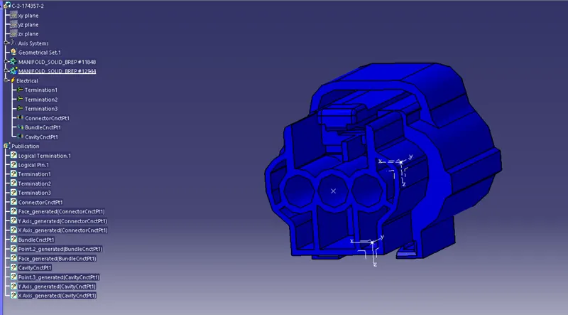
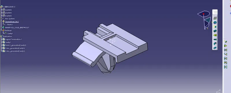
TYCO 85229-1
- Create a midpoint
- Create a cavity connection point
- Create a cavity connection axis system orieentation should be same as in connector
- Switch to the Electric part design and define part as mounting equipment
- Define the cavity connection point
ELECTRIC ASSEMBLY DESIGN
- Impot connector and cavity/mounting clip
- Select the defing the electric connector
- Select cavity and then connector