Wiring harness design in CATIA V5 - 3D modeling Week 2 Challenge
Report:
Objective:
- To define the electrical properties of Connectors and connectors clip using Electrical Part Design.
- A connector is a coupling device that joins electrical terminations to create an electrical circuit. We design and manufacture an expansive portfolio of electrical connector types that are engineered to reliably transmit data, power, and signal in the harshest environments, under the most extreme use.
- Connectors enable contact between wires, cables, printed circuit boards, and electronic components. Our different types of connectors including PCB connectors and wire connectors are manufactured to reduce application size and power usage while enabling increased performance.
Electrical Components:
- Deutsch DT06 – 08SA
- Tyco 174357-2
Mounting Components:
- Tyco 85229-1
Design Methodology:
1.Deutsch DT06 – 08SA
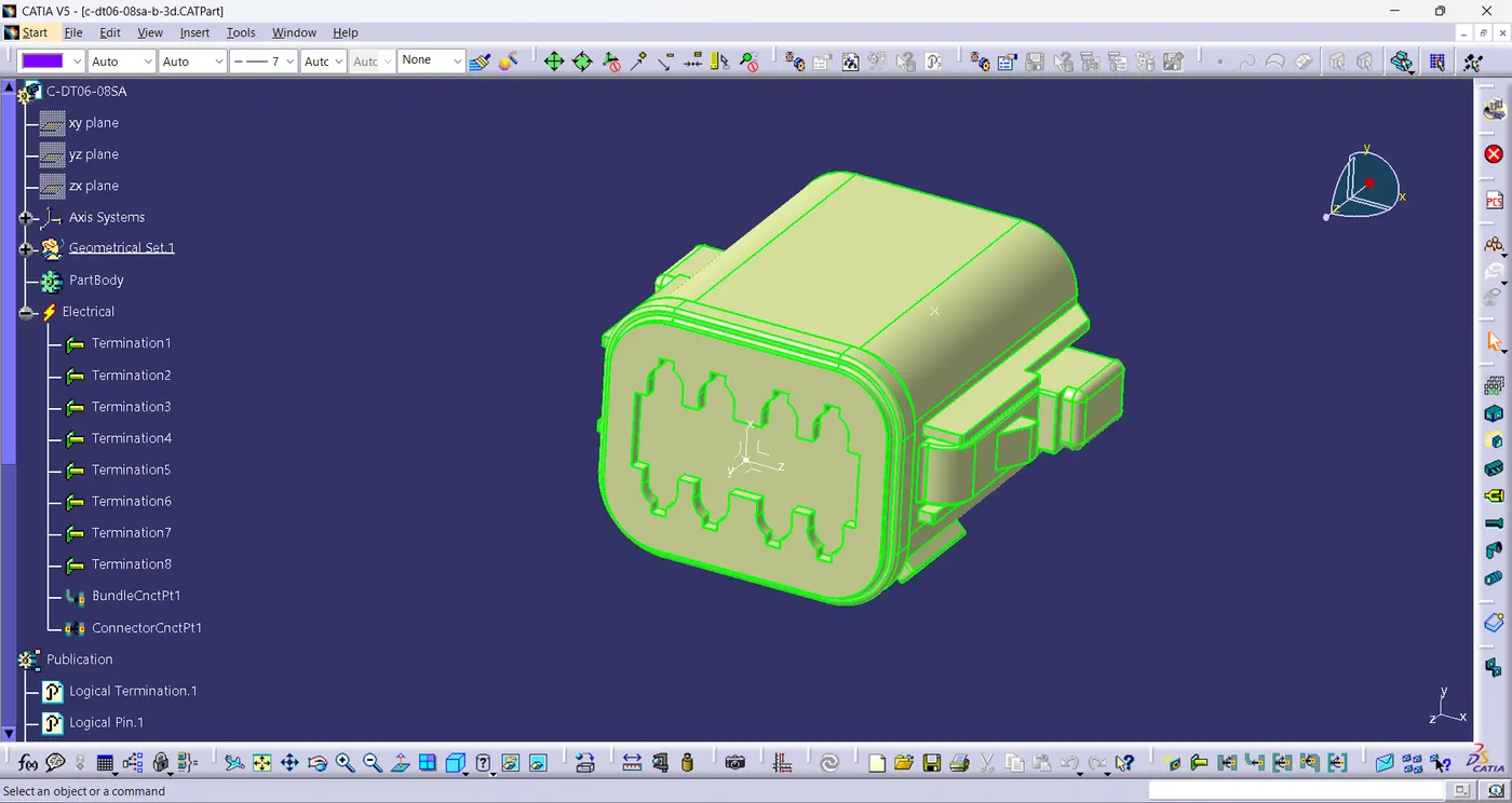
- First step is to download the .igs file and convert it into .CATPart file.
- The required geometrical parameters like point, axis on the mating face of the connector are defined.
- Then Define the Connector using define connector command in which we assign the no. of terminals and select the body.
- Define Bundle connection point by selecting representation and initial condition as the normal face and select the midpoint as point.
- Define Connector connection point by selecting mid-point as representation ,mating face ,Coincidence & orientation axis.
- Save the file and the connector is fully defined with all the necessary electrical properties.
2.Tyco 174357-2
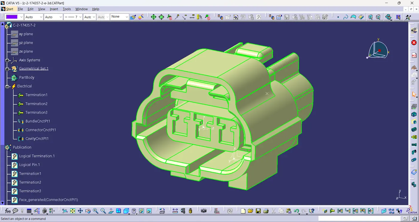
- First step is to download the .igs file and convert it into .CATPart file.
- The required geometrical parameters like point, axis on the mating face of the connector are defined.
- Then Define the Connector using define connector command in which we assign the no. of terminals and select the body.
- Define Bundle connection point by selecting representation and initial condition as the normal face and select the midpoint as point.
- Define Connector connection point by selecting mid-point as representation , connector mating face ,Coincidence & orientation axis.
- Create the point on the mating face of connector with clip and assign the axis system by selecting the point as origin.
- Define the cavity connection point and the connector is fully defined with all the necessary electrical properties.
3.Tyco 85229-1
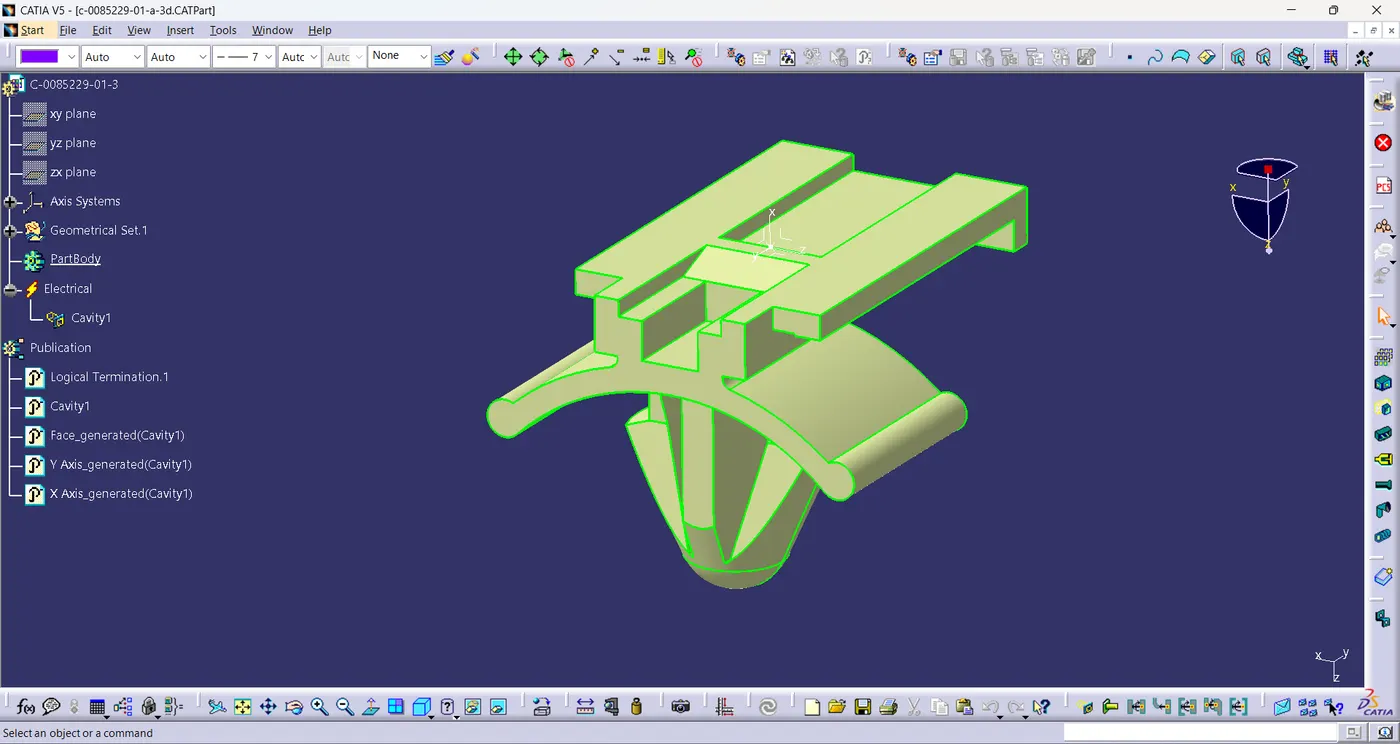
- Create the point on the mating face of clip with connector and assign the axis system by selecting the point on the mating face of clip as origin.
- Define the body as mounting equipment using the command define mounting equipment by selecting the body.
- Define the equipment as cavity by selecting the point on the mating face of clip as representation, clip mating face ,Coincidence & orientation axis.
- Save the file and the clip is fully defined with all the necessary electrical properties.
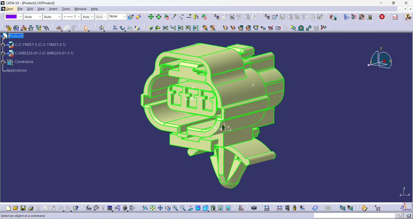
Assembly Of Connecter and Clip:
- Connecter and clip are assembled together using connect electrical devices command by selecting cavity connection point and representation point of cavity.
Conclusion:
- All the necessary electrical properties of connectors and connectors clip are defined using electrical part design workbench.
- The connector and connector clip are also assembled.