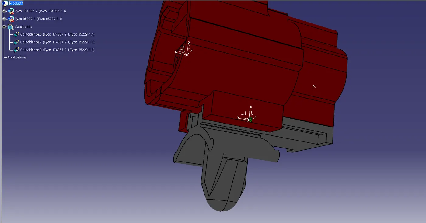
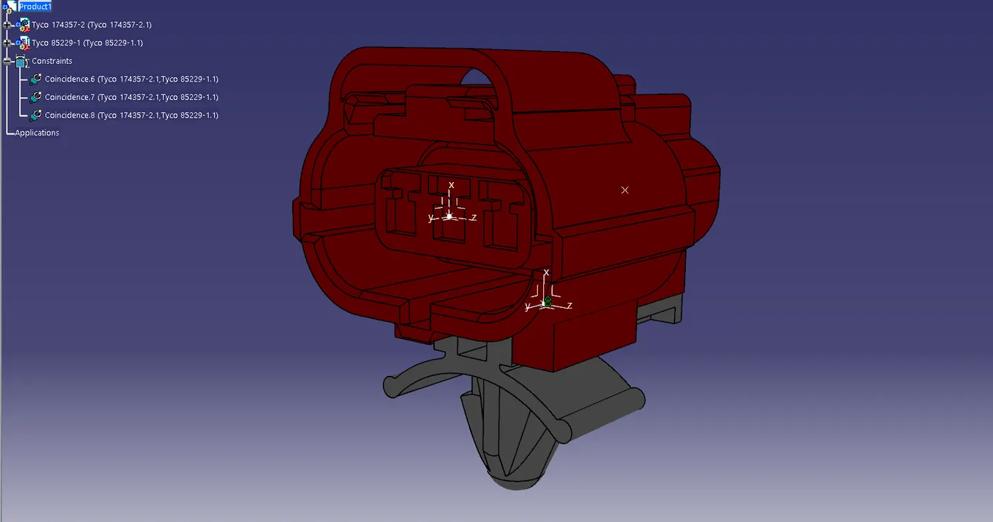
Wiring harness design in CATIA V5 - 3D modeling Week 2 Challenge
DEFINING CONNECTORS & CLIPS
AIM :-
to define the given connectors and clamps with its electrical properties.
OBJECTIVE :-
download the cad data of the given connector and clip from the te.com web site and define them with required electrical properties. and create required catalogues and add the connectors and clip to them for future using.
Given Components
connectors 1. Deutsch DT06 – 08SA
2. Tyco 174357-2
Clip 1. Tyco 85229-1
CONNECTORS ( Deutsch DT06 – 08SA & Tyco 174357-2 )
- First downloaded the cad files in igs format from the link provided for te.com web site and save it.
- after identifiy the connector and bundle connection side, defines the required grometrical parameters line conter point and axis system which is required for defining the connector connection point and bundle connetion point.
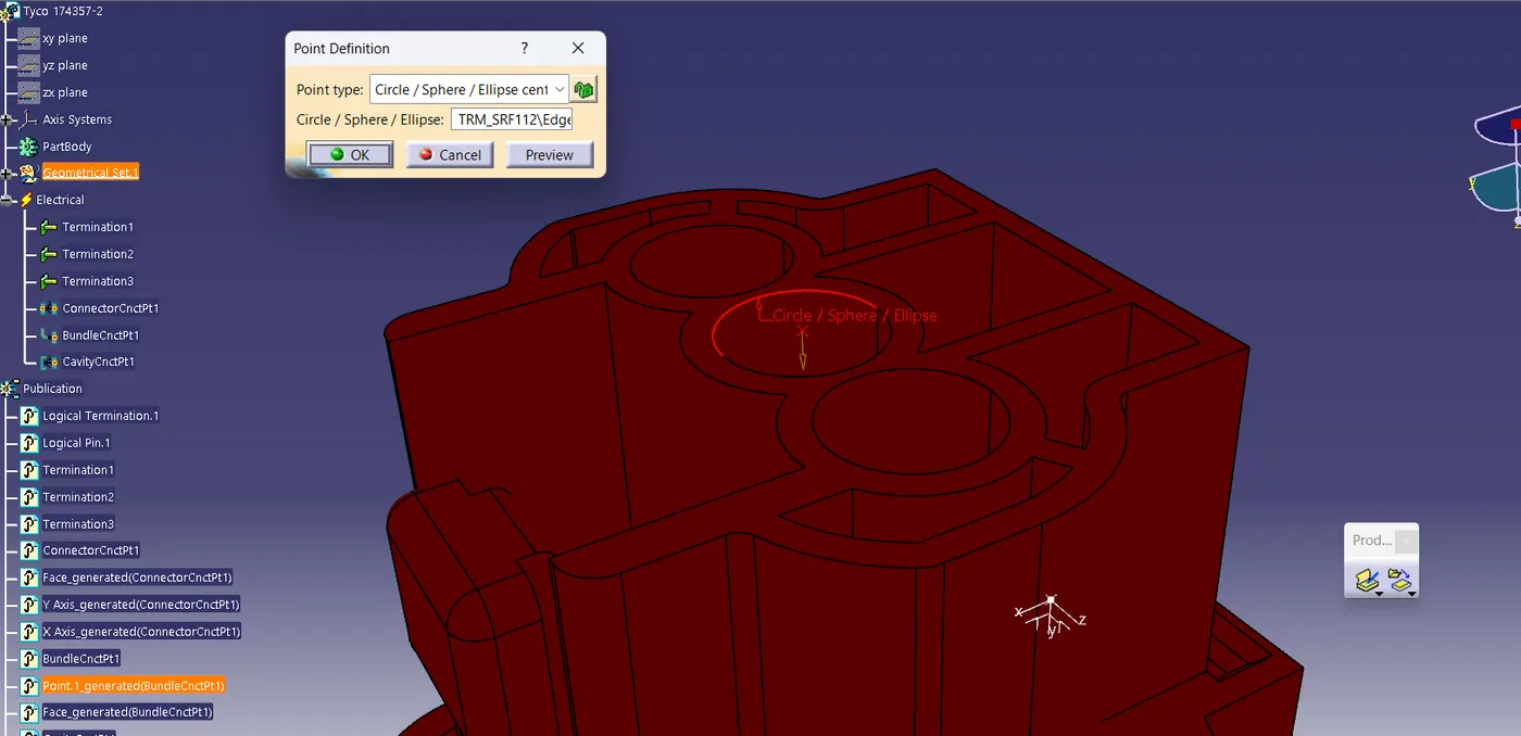
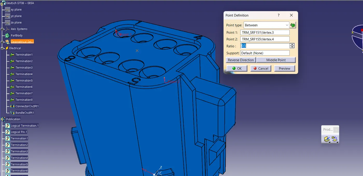
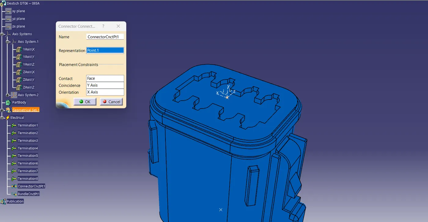
- when placing the axis system there is no defined rulrs for axis direction but we should follow a same method for all the components for avoiding the trouble during assembley. so here we place the Y axis in the direction connector connecion, X axis towards the locking position and z axis to the other side.
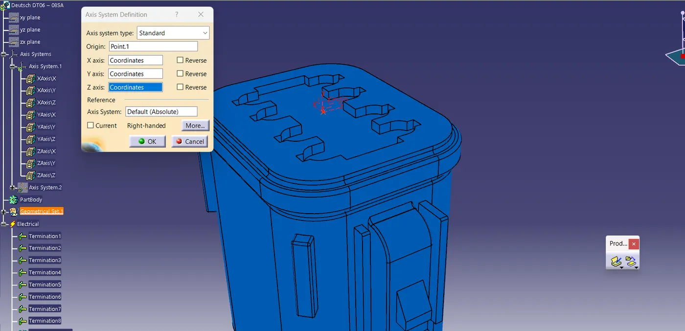
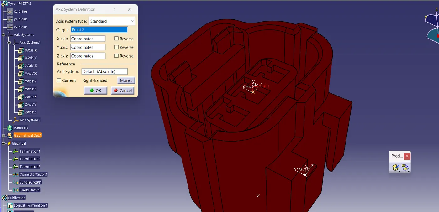
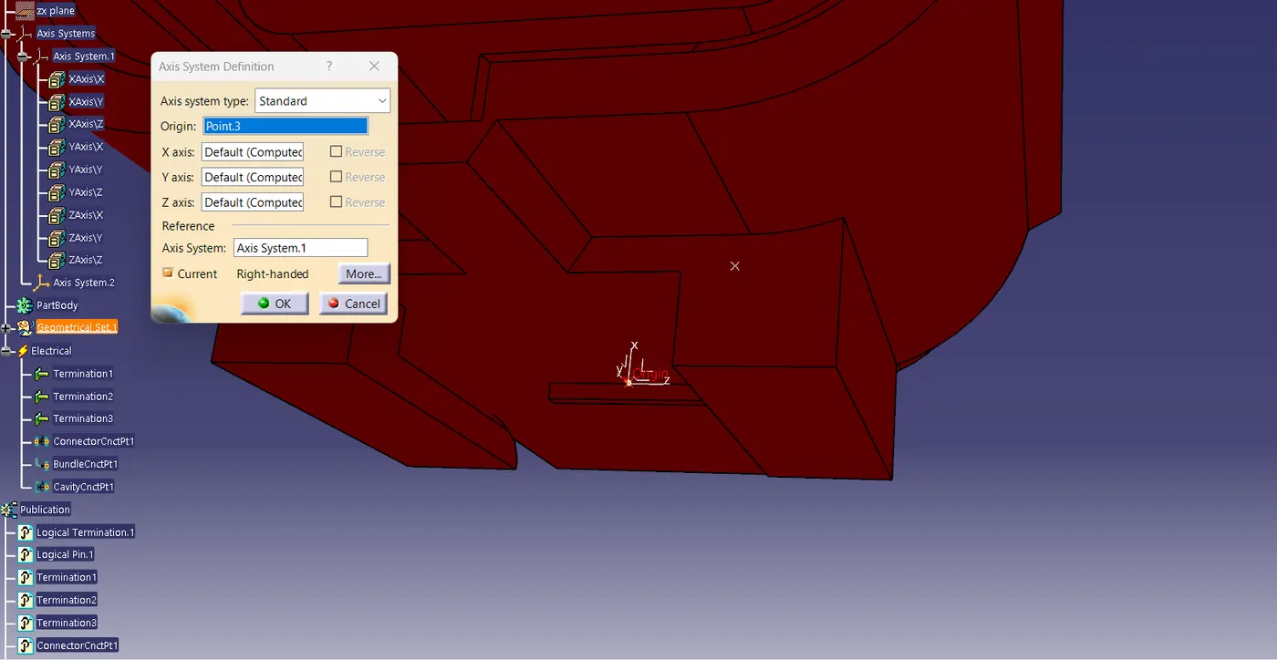
- in case of Tyco 174357-2 connnector it has provided with a point for fixing the mounting clip so we have provide this connector with a cavity connection point which is same as the connector connection point.
-
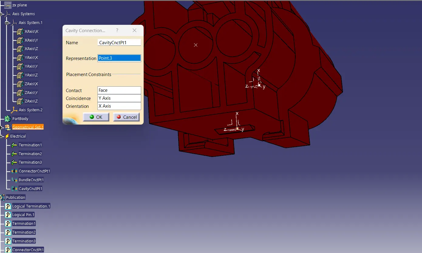
for creating cavity connction point we required a contact face, representation point and a axis system in a way thet the y axis direction towards the meeting, x axis towards the locking direction and z axis towards the left or right.
- after the required grometrical parameters has given define the connectors with the type of connector and number terminals.
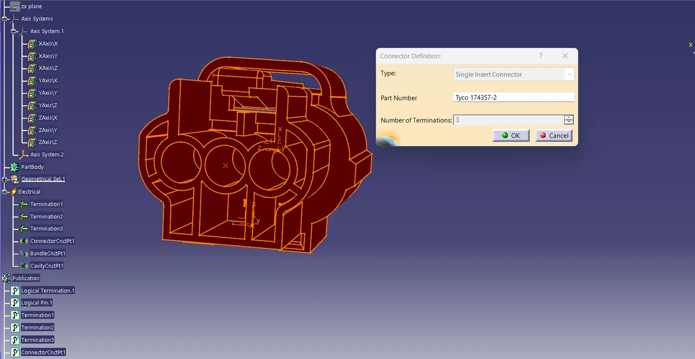
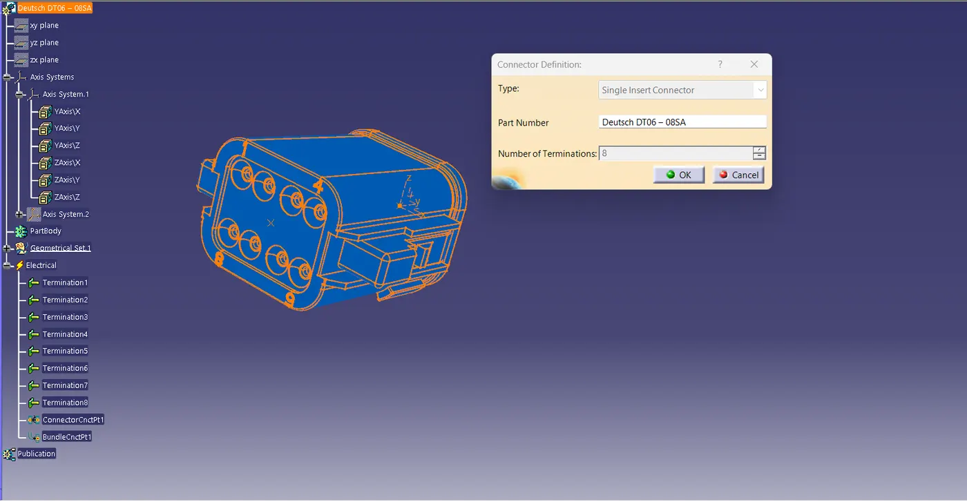
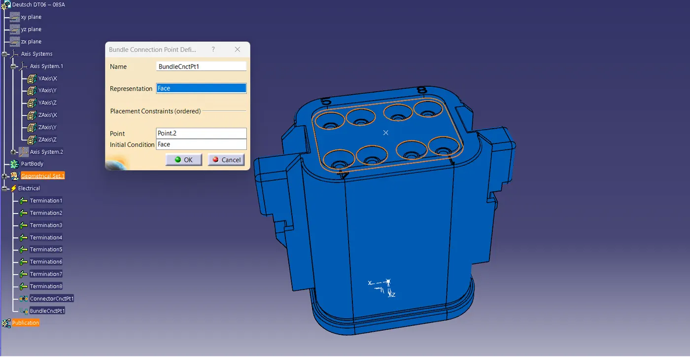
- next step is to define the connector connection connection point and bundle connection point.
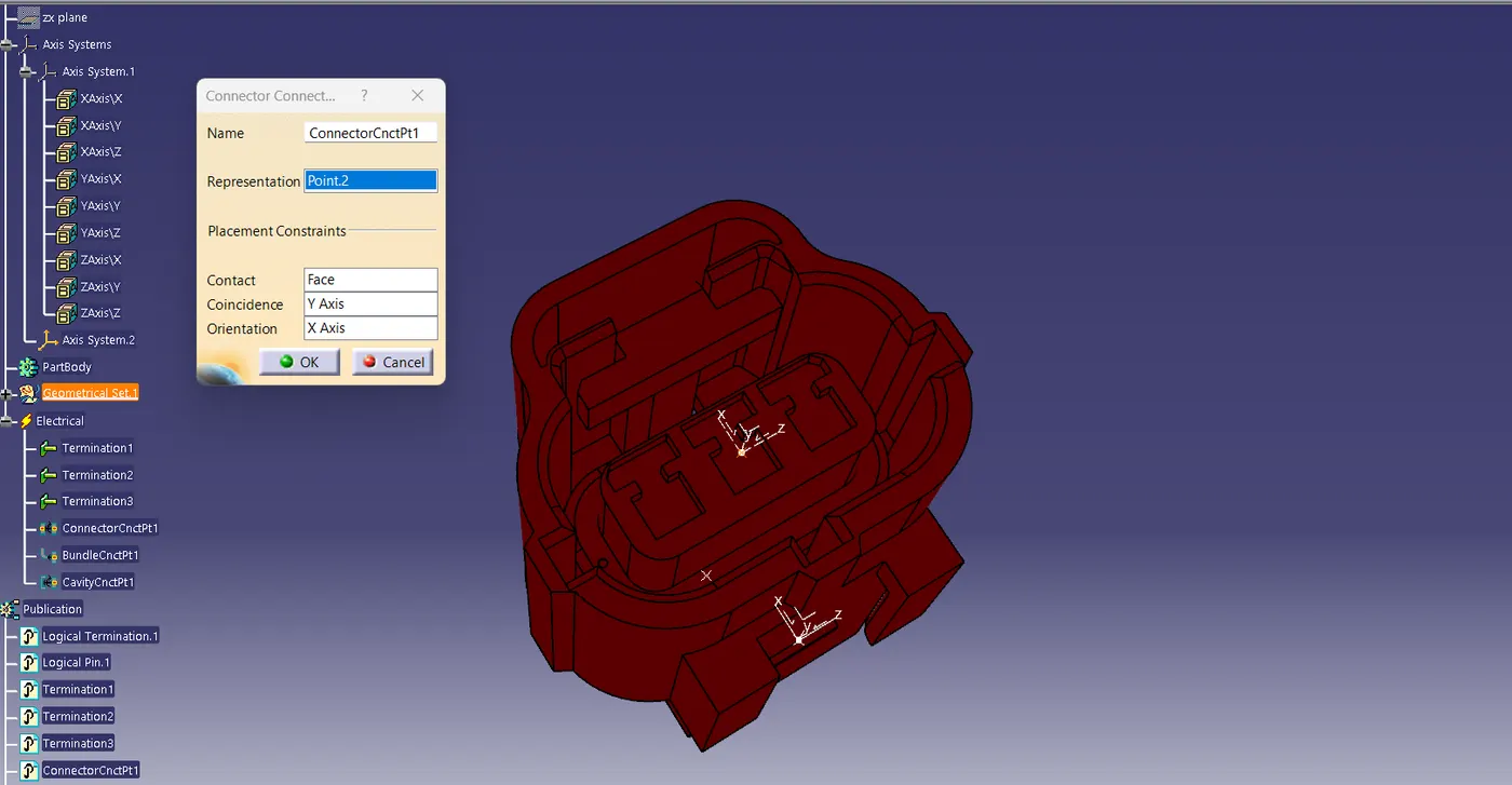
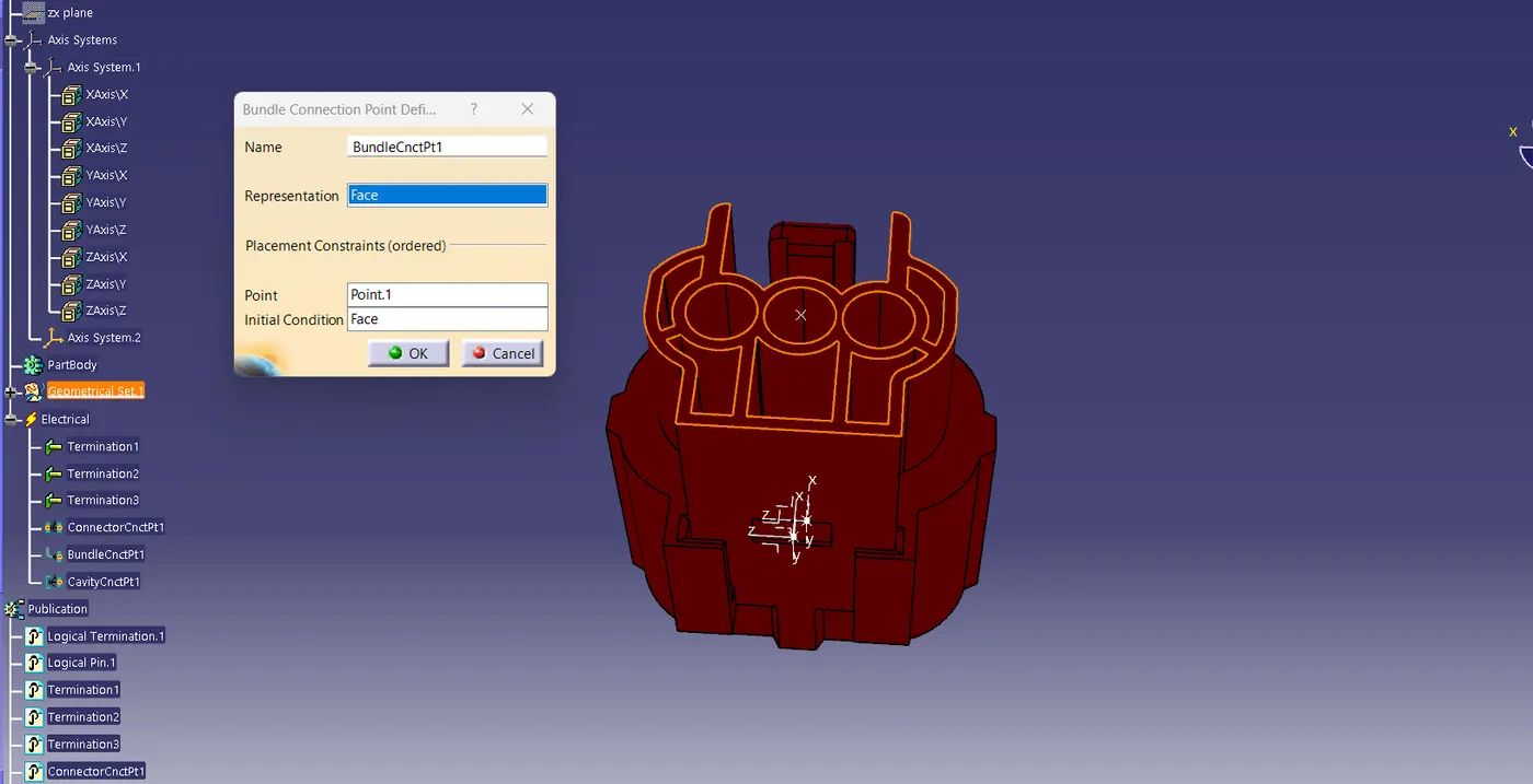
- for the Tyco 174357-2 connector we need to define the cavity connection point
CLIP(Tyco 85229-1)
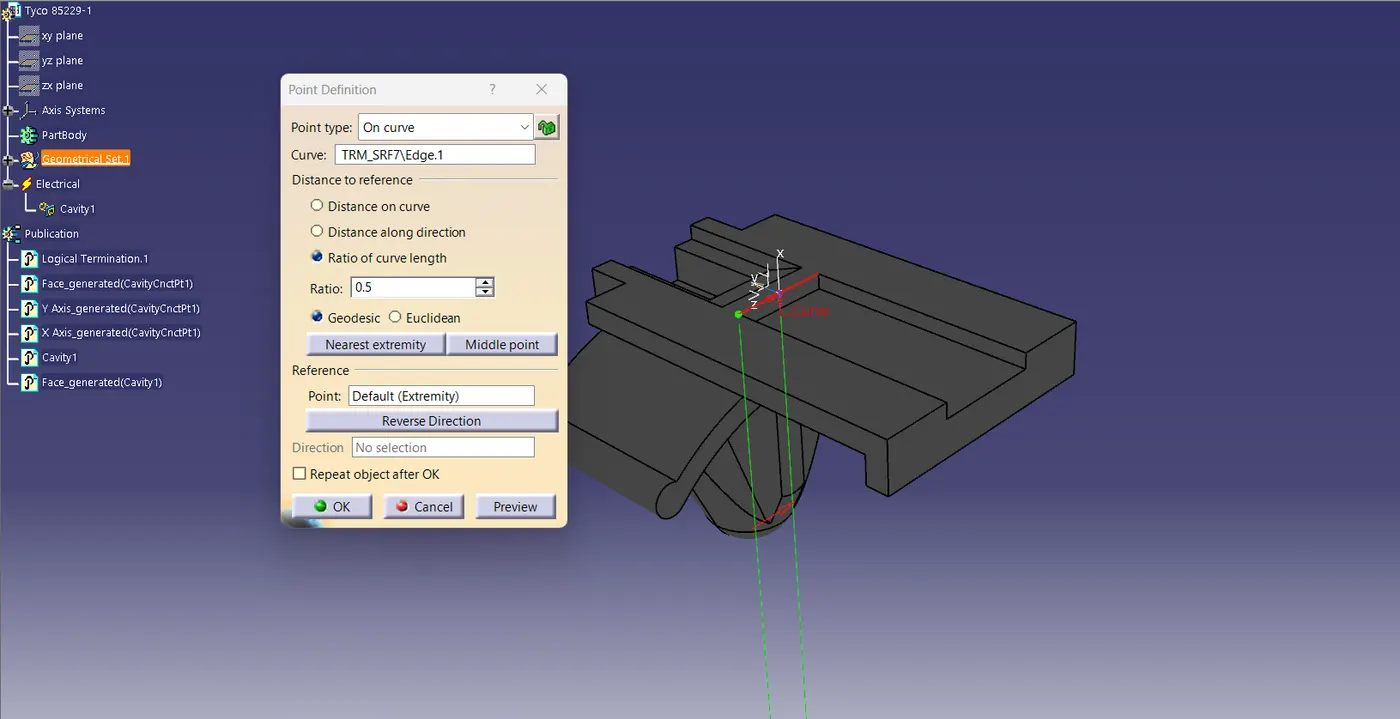
- After downloading and saved the clip file, create the required geometrical parametrs which is a point and axis system on the mating surface.
- When creating axis system we follow the directions same as we give in its pair part which is Tyco 174357-2 connector.
CATALOGUE CREATION
After defining the electrical properties we created catalogue files add familyes accordingly to save the electricaly defined components so it will help full for future use for ourself and other persons who can use it.
we have created 2 calalogue files tthey are
- connector
- clips
CLIP AND CONNECTOR ASEMBLEY