Wiring harness design in CATIA V5 - 3D modeling Week 2 Challenge
Wiring Harness Design in Catia V5 - 3D Modeling Week 2 Challenge
OBJECTIVE: To define all the necessary properties for connectors and clip by downloading the given connectors and connector clip CAD data from the provided link.
1. Deutsch DT06-08SA ( https://www.te.com/usa-en/product-DT06-08SA.html)
2. Tyco 174357-2 (https://www.te.com/usa-en/product-2-174357-2.html?source=header-match)
3. Tyco 85229-1 – (https://www.te.com/usa-en/product-85229-1.html?q=85229&source=header)
MAIN PROJECT - 1:
I) Connector - 1 (DT06-08SA):
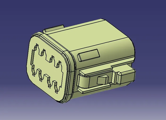
Given CAD Data:
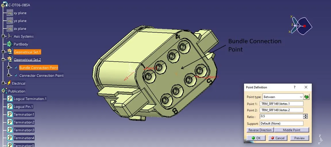
STEP-1: Bundle Connection Point
Create a midpoint on the contact face which is normal to bundle wire direction.
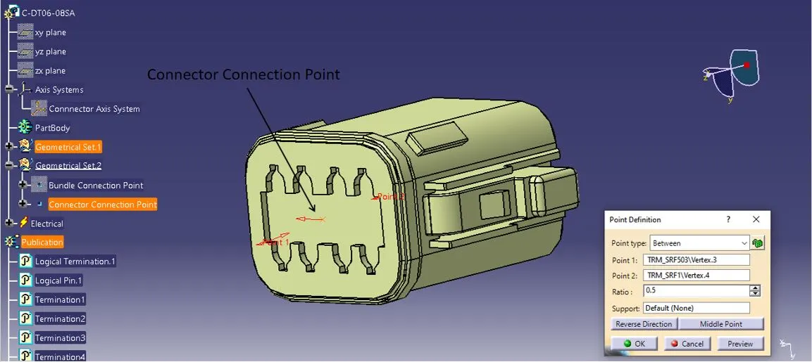
STEP-2: Connector Connection Point
Create a centre point on the connector pin in a way that the connecting male/female connector has to be aligned properly.
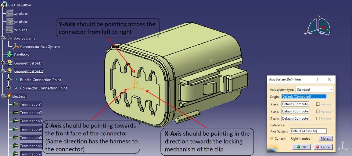
STEP-3: Connector Axis System
Create an Axis System on the connector connection point as defined below.
Switch from Mechanical Part Design Workbench to Electrical Part Design Workbench
STEP-4: Define Connector
Define the CAT Part as a connector using the Define Connector option and mention the type of connector and terminations based on the no. of wiring inputs present in the connector.
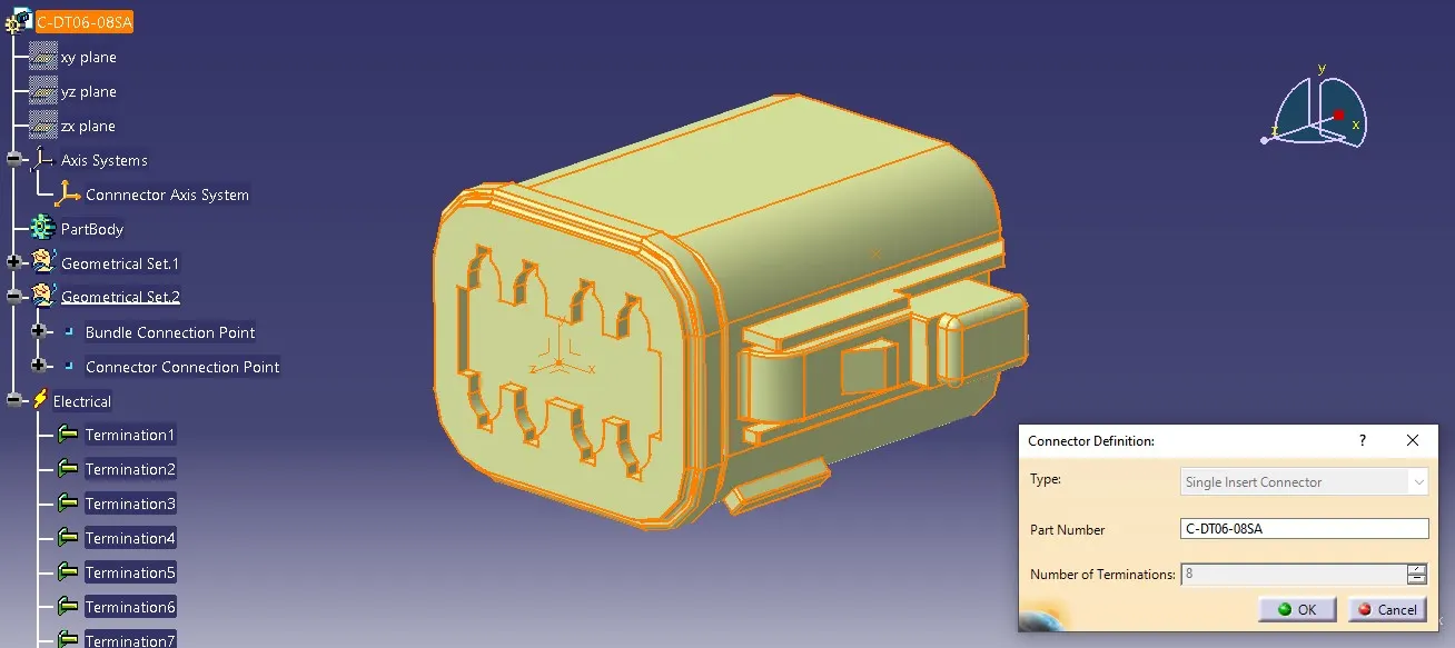
STEP-5: Define Bundle Connection Point
Choose the Define Bundle Connection Point option. Select the bundle wire contact face as a representation and define placement constraints.
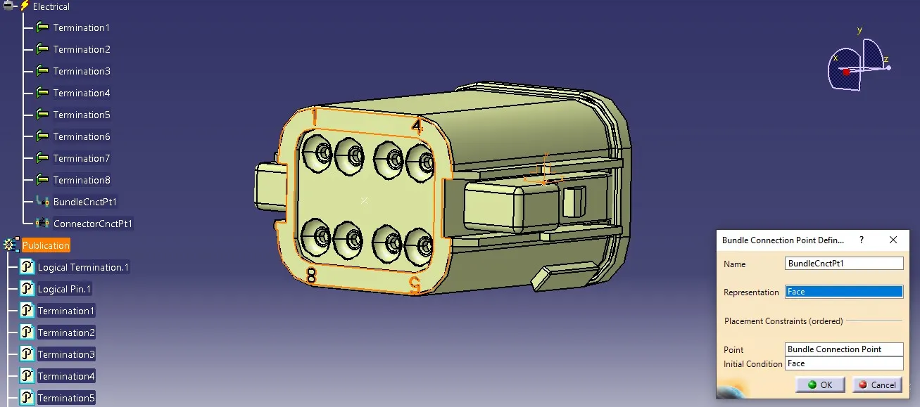
STEP-6: Define Connector Connection Point
Choose the Define Connector Connection Point option. Select the connector connection point as representation and define placement constraints as below.
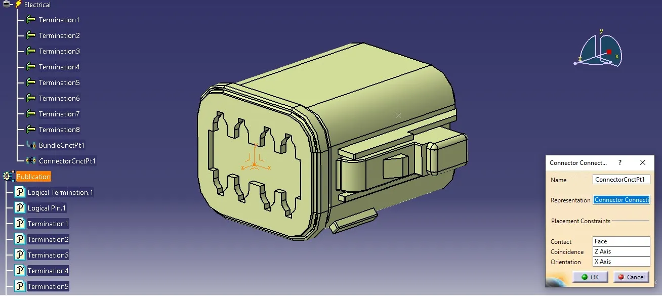
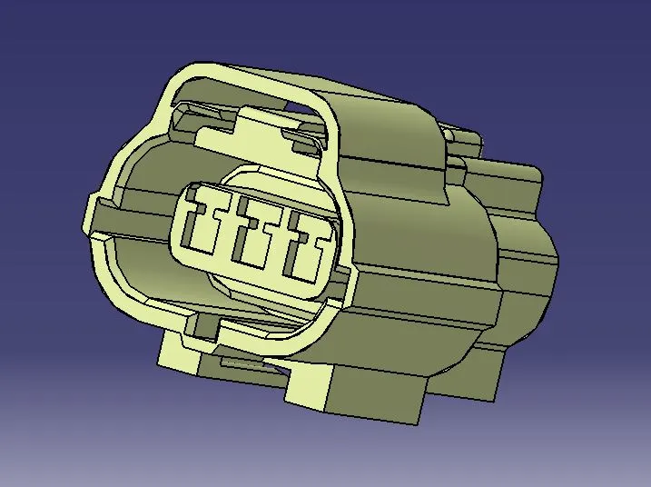
II) A) Connector - Tyco 174357-2:
Given Data:
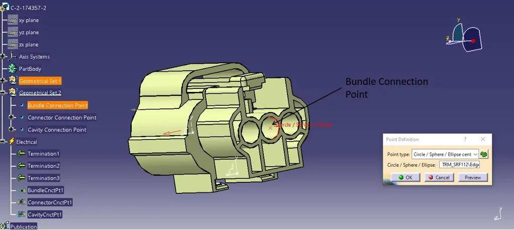
STEP-1: Bundle Connection Point
Create a midpoint on the contact face which is normal to bundle wire direction.
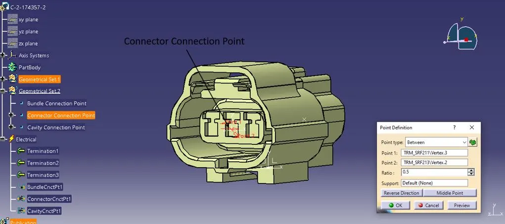
STEP-2: Connector Connection Point
Create a centre point on the connector pin in a way that the connecting male/female connector has to be aligned properly.
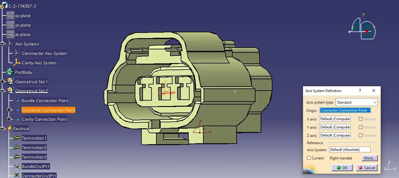
STEP-3: Connector Axis System
Create an Axis System on the connector connection point as defined already.
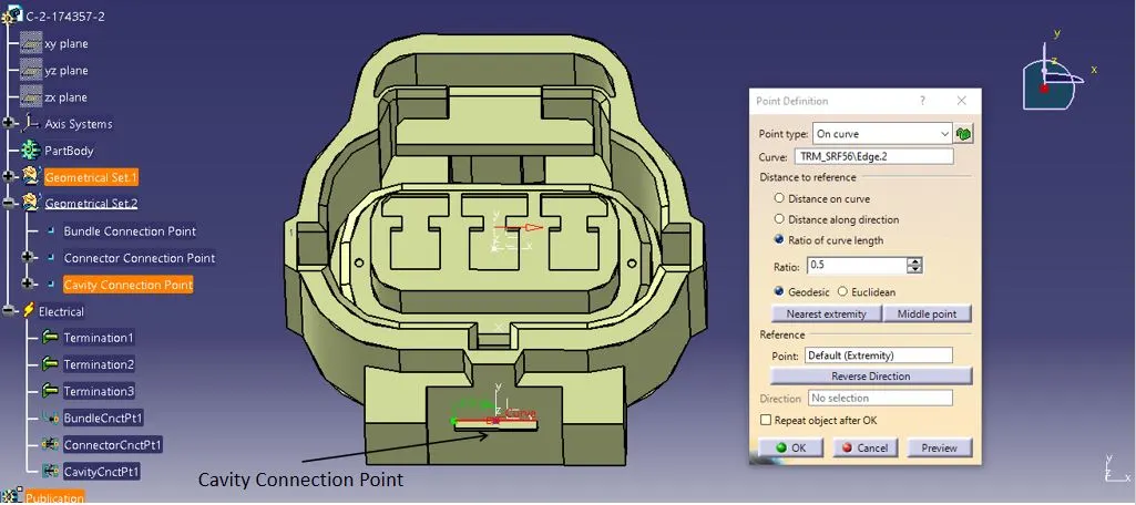
STEP-4: Cavity Connection Point
Create a centre point on the cavity lock connector area in a way that the mounting clip has to be aligned properly.
STEP-5: Cavity Axis System
Create an Axis System on the cavity connection point as similarly created for the connector.
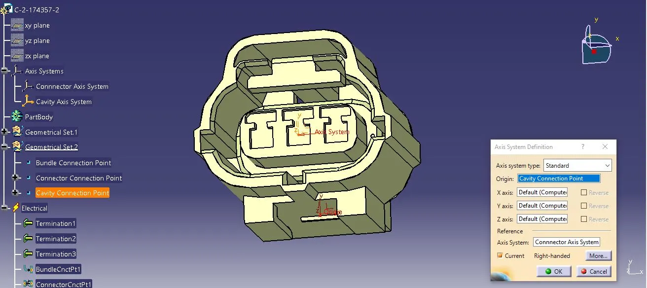
Switch from Mechanical Part Design Workbench to Electrical Part Design Workbench
STEP-6: Define Connector
Define the CAT Part as a connector using the Define Connector option and mention the type of connector and terminations based on the no. of wiring inputs present in the connector.
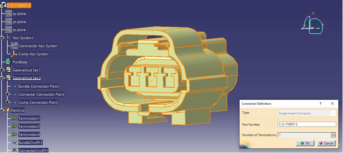
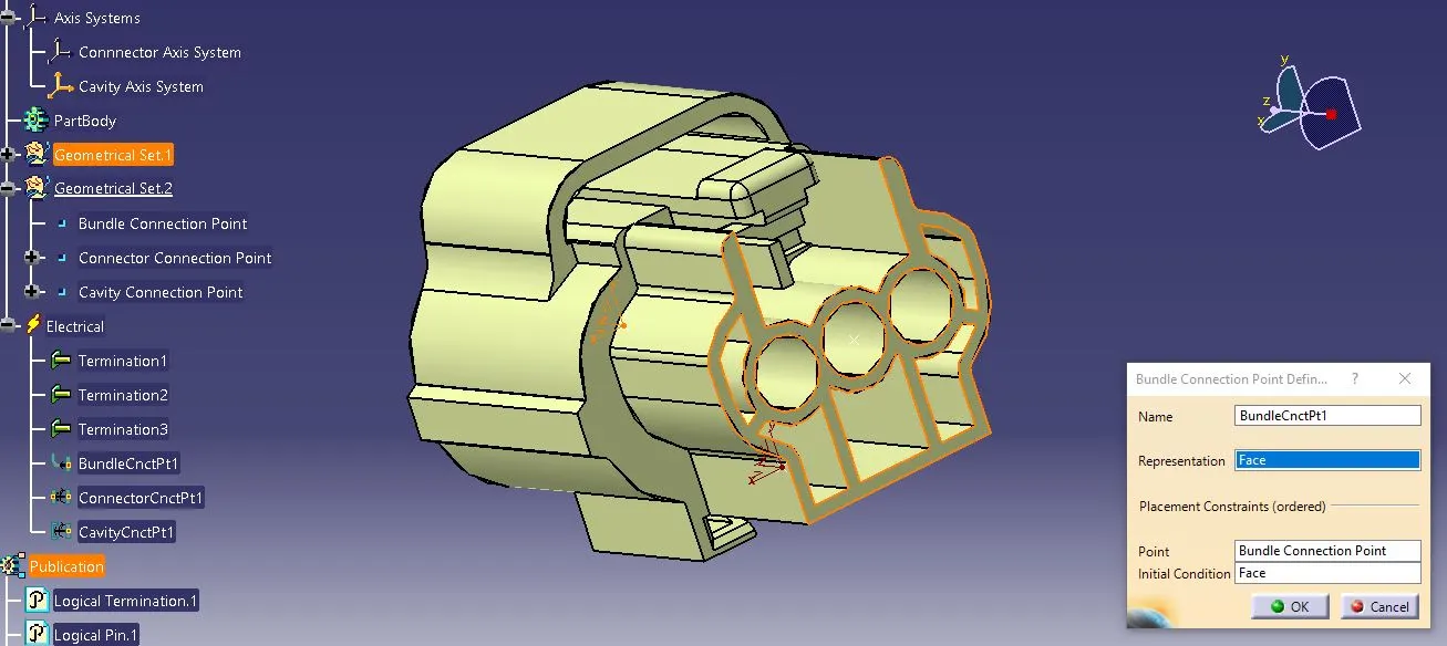
STEP-7: Define Bundle Connection Point
Choose the Define Bundle Connection Point option. Select the bundle wire contact face as a representation and define placement constraints.
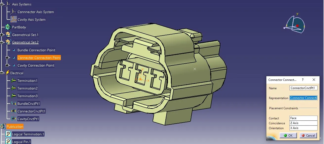
STEP-8: Define Connector Connection Point
Choose the Define Connector Connection Point option. Select the connector connection point as representation and define placement constraints as below.
STEP-9: Define Cavity Connection Point
Choose the Define Cavity Connection Point option. Select the cavity connection point as representation and define placement constraints as below.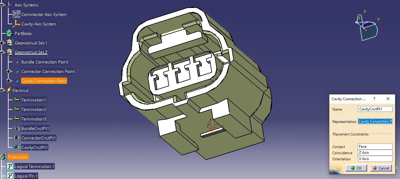
B) Cavity - Tyco 85229-1:
Given Data:
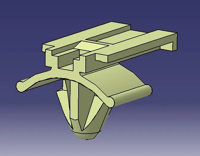
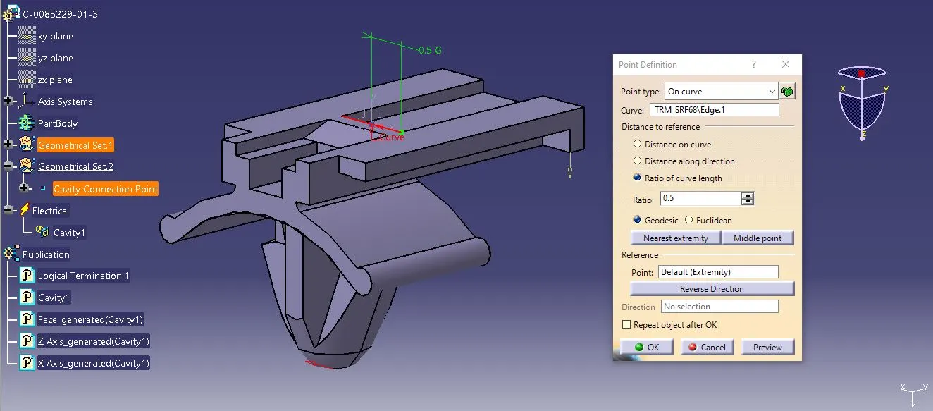
STEP-1: Cavity Connection Point
Create a midpoint on the edge which contacts with the respective connector as a locking mechanism such a way that both the mounting clip and connector are aligned properly.
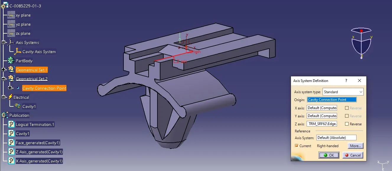
STEP-2: Cavity Axis System
Create an Axis System on the cavity connection point as similarly created on the connector part.
Switch from Mechanical Part Design Workbench to Electrical Part Design Workbench
STEP-3: Define Cavity:
Define the CAT Part as a cavity using the Define Cavity option and mention the representation as Cavity Connection Point and define the placement constraints. 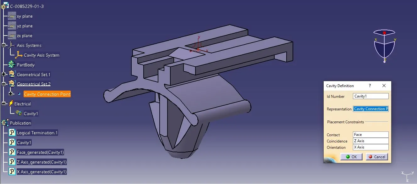
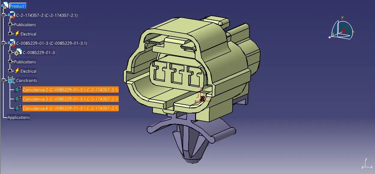
NOTE: It is sufficient to properly mate the cavity and connector if the cavity connection point is already defined in the connector component, therefore there is no need to define it in the cavity part.
C) Assembly:
Switch from Electrical Part Design Workbench to Electrical Assembly Design Workbench
STEP-1: Define First import both the connector and the mounting clip into the product file and with the use of the Connect Electrical devices option select the cavity and select the cavity connection point in the connector part. The mounting clip and the connector will align based on the defined constraints in both parts.
Conclusion:
Thus the given connectors and connector clip CAD data are downloaded and all the necessary properties are defined and connected them using Catia V5.