Wiring harness design in CATIA V5 - 3D modeling Week 2 Challenge
OBJECTIVE
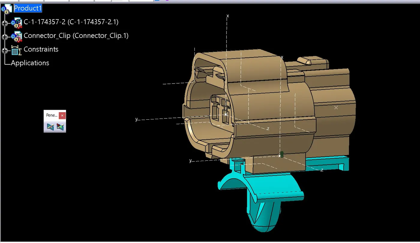
Define given connector and connector clip as Electrical Connector and clip using Electrical Part design Workbench. Define all the necessary properties to Connectors & Clip.
Wiring harness introduction
The term wiring harness refers to the assembly of
- Wires
- Connectors
- Terminals
- Protection coverings
- Insulations
- Clips & clamps
- Fuse & relay box
- Retention devices
- Guiding channels
- Electronic components
Terminologies & Definitions
Electrical Schematics
Electrical schematic is detail design of Logical schematics which describes the pin to pin connectivity, Properties, Fusing distribution, Grounding distribution, Interconnects, Wire properties, Circuit properties, Specification of components etc. This is the end result of Electrical core design of system and used as a primary input for Harness design.
Wiring harness Topology
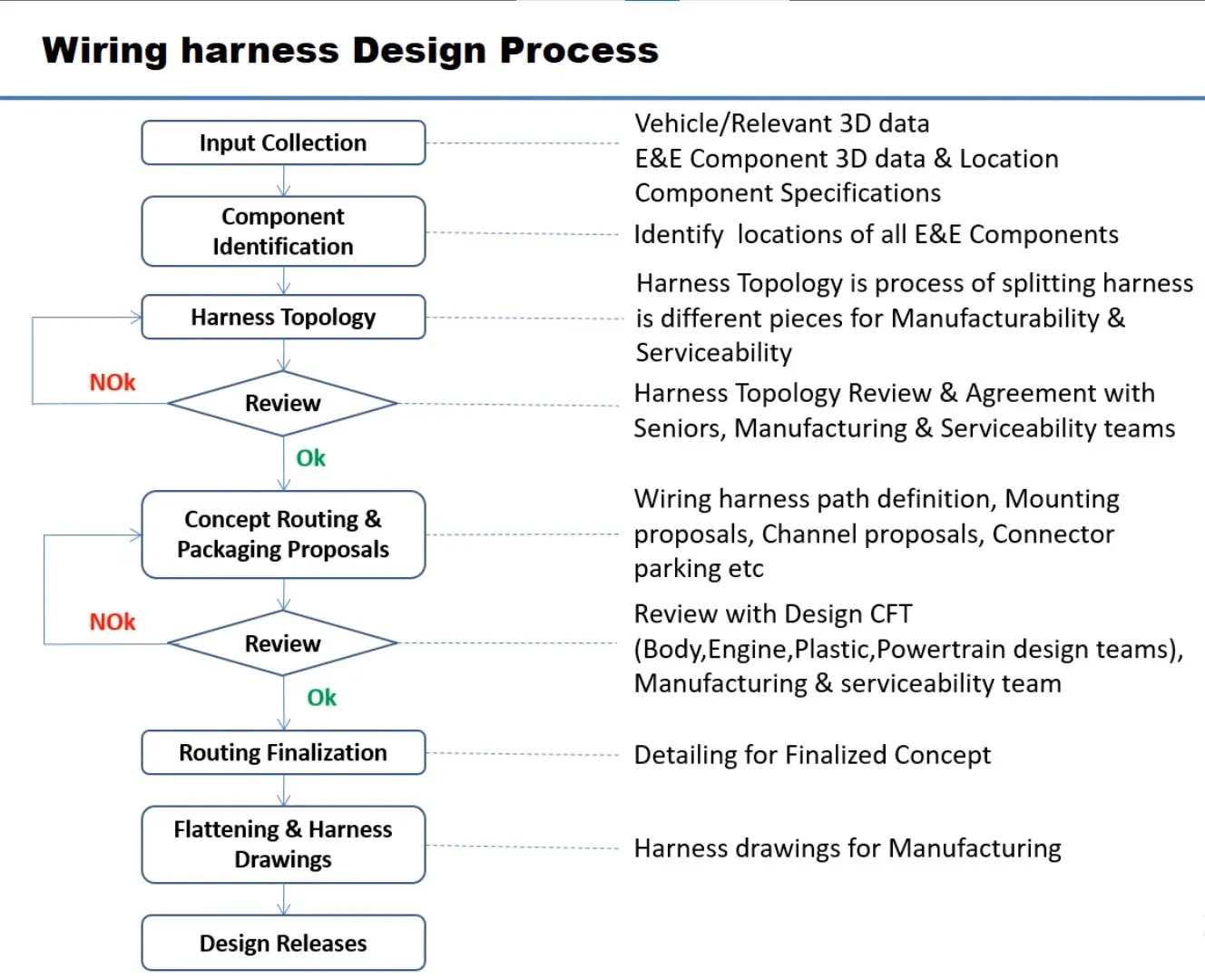
Wiring harness Topology is strategy to divide or Split the harness between different pieces to achieve the best Manufacturability, Serviceability & Cost effective design.
Wiring harness Routing
Wiring harness routing deals with desired path of wiring harness into given vehicle environment by applying set of design rules & industry best practices.
Wiring harness Packaging
Wiring harness packaging deals with Fixing/Mounting strategy of wiring harness routing to ensure the safe, Reliable & Durability of wiring harness by applying set of design rules & industry best practices.
CONNECTORS
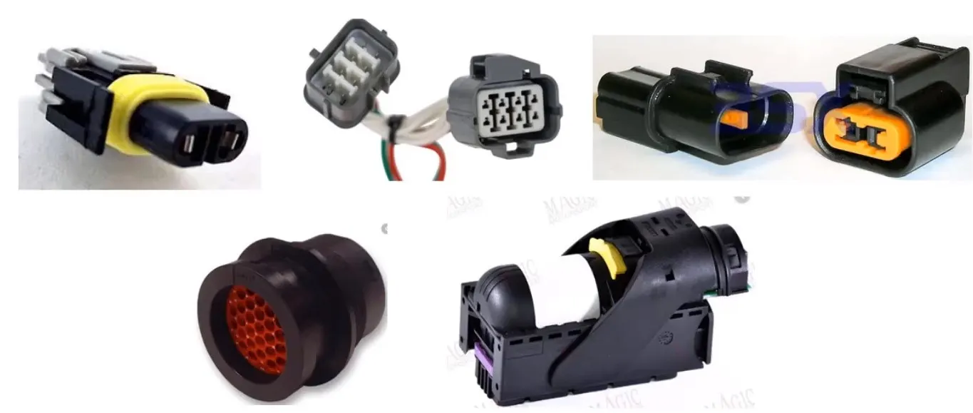
An electrical connector is an electro-mechanical device used to join Electrical termination and create an electric circuit. Electrical connectors consist of Housing, Terminals, Wedge Locks, Seals, Cavity, and Mounting Cam etc.
Connectors are Plastic molded housing with locking & Retention features
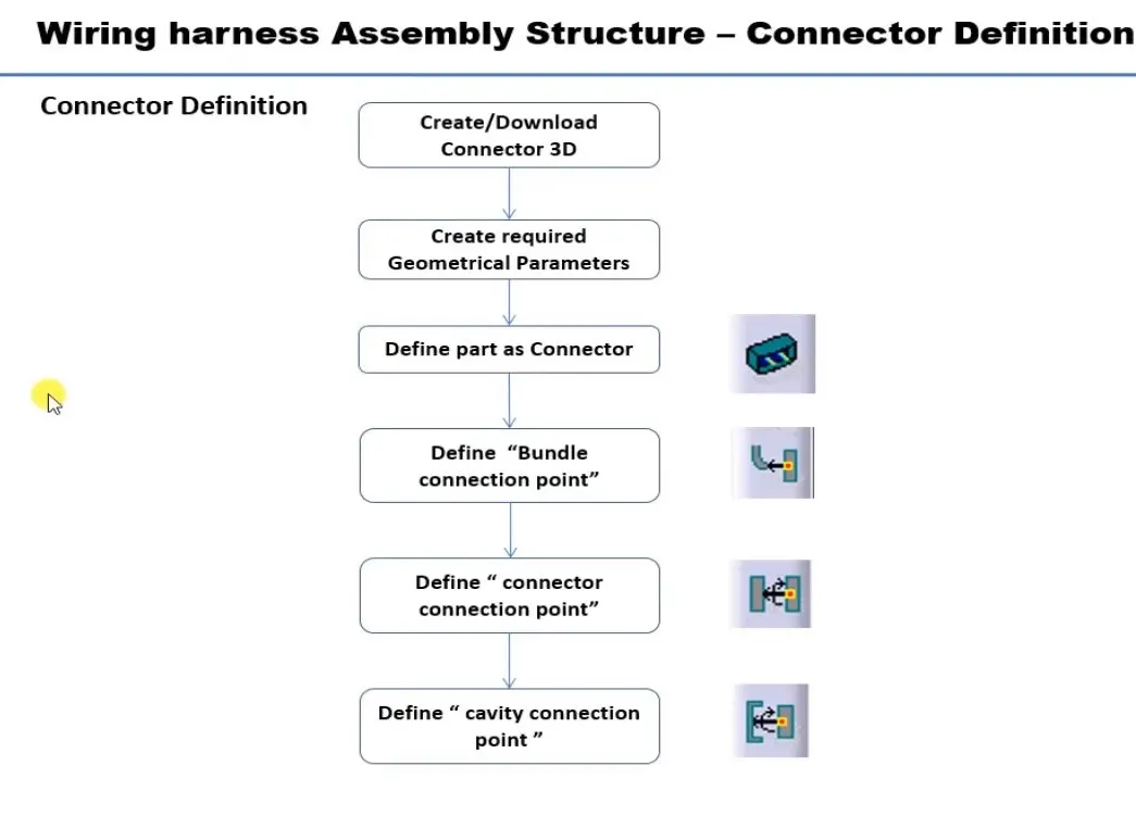
CONNECTOR DEFINITIONS IN CATIA V5
1. Deutsch DT06 – 08SA
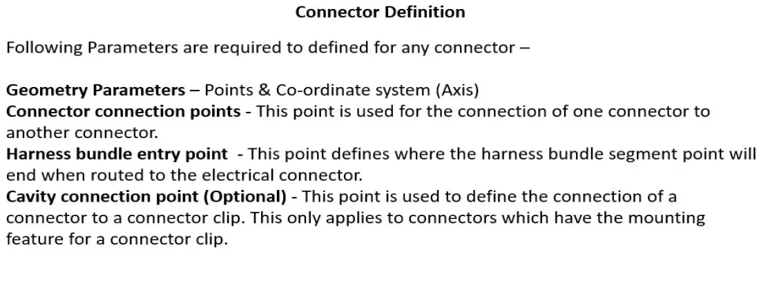
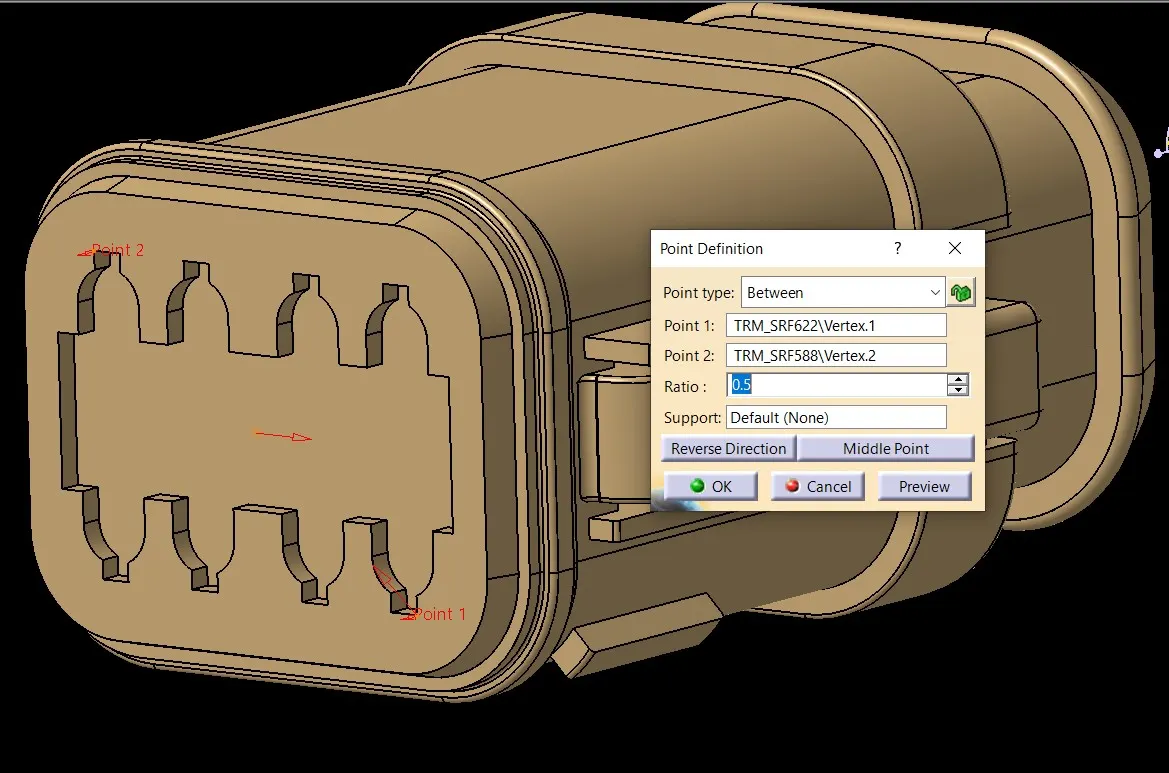
Connector connection point:
Create midpoint on the contact face which will be normal to wire bundle insertion.
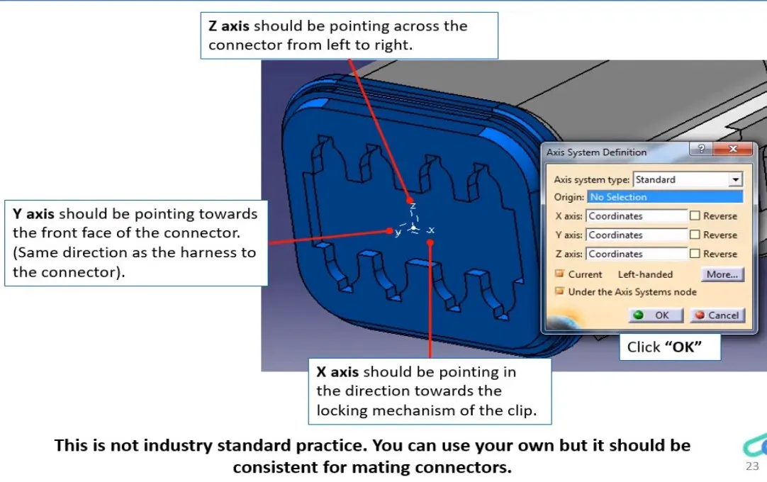
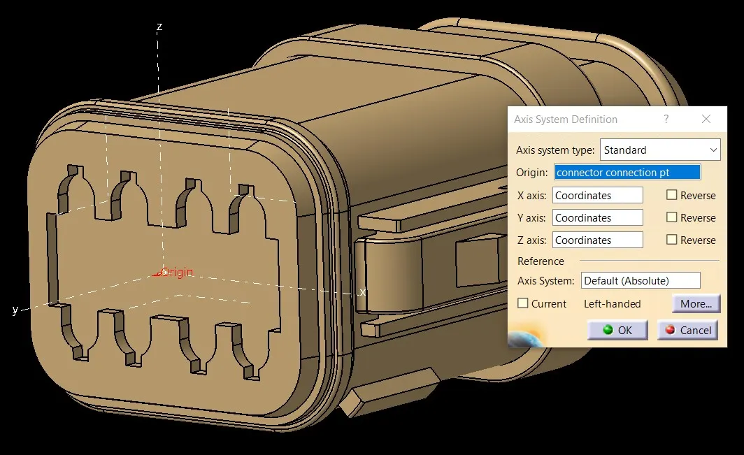
Craete Axis System with respect to the point which we have created and defining the axis direction as shown below
Bundle connection point:
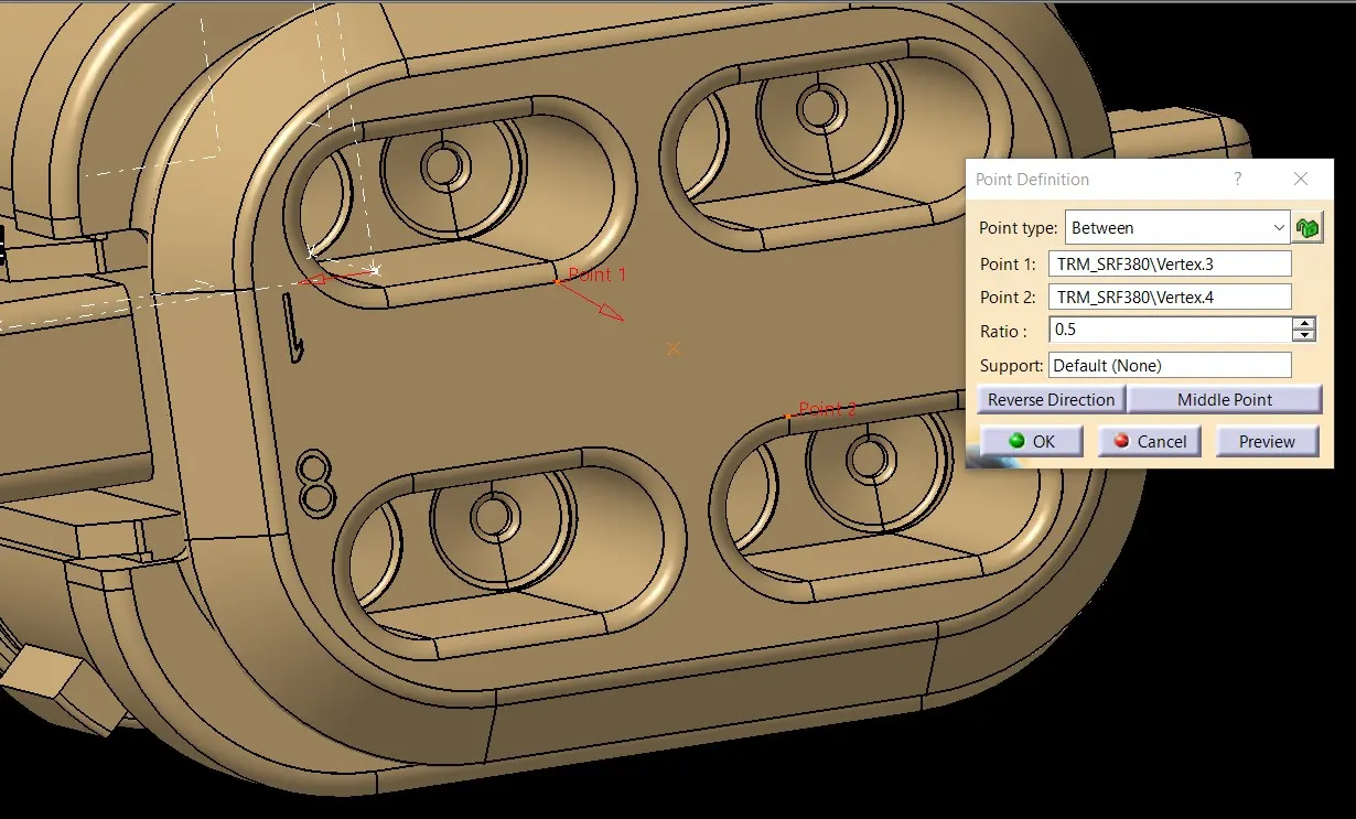
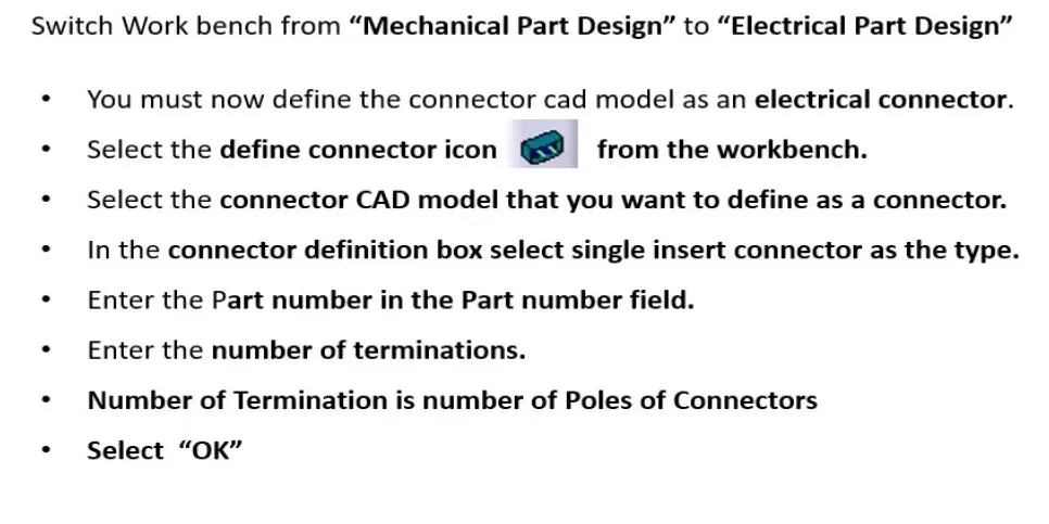
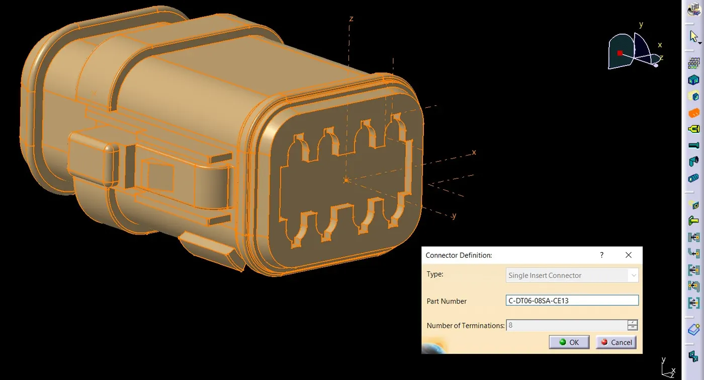
Define Bundle connection point
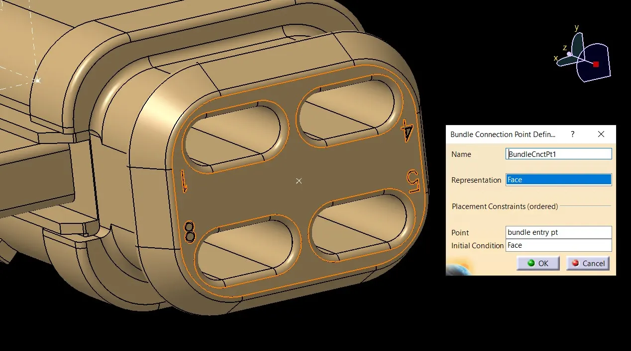
Define connector connection point
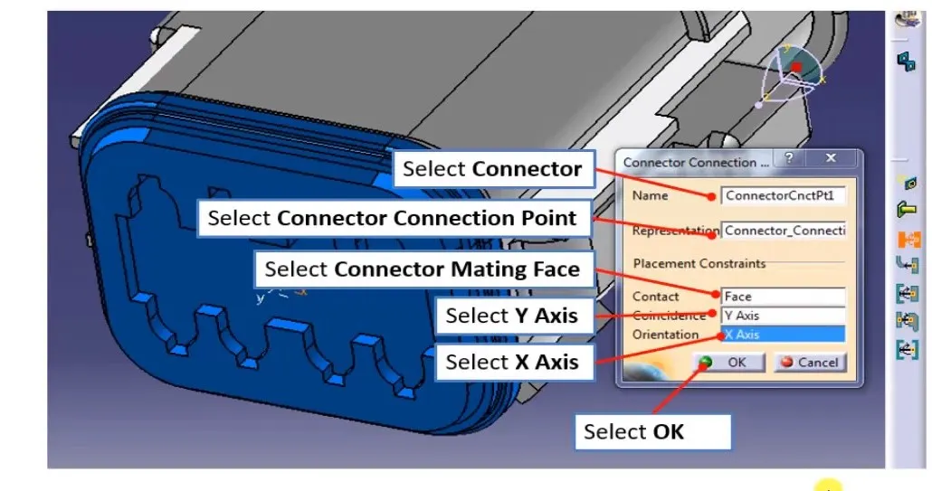
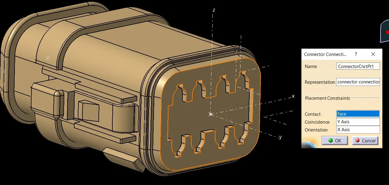
2.Tyco 174357-2
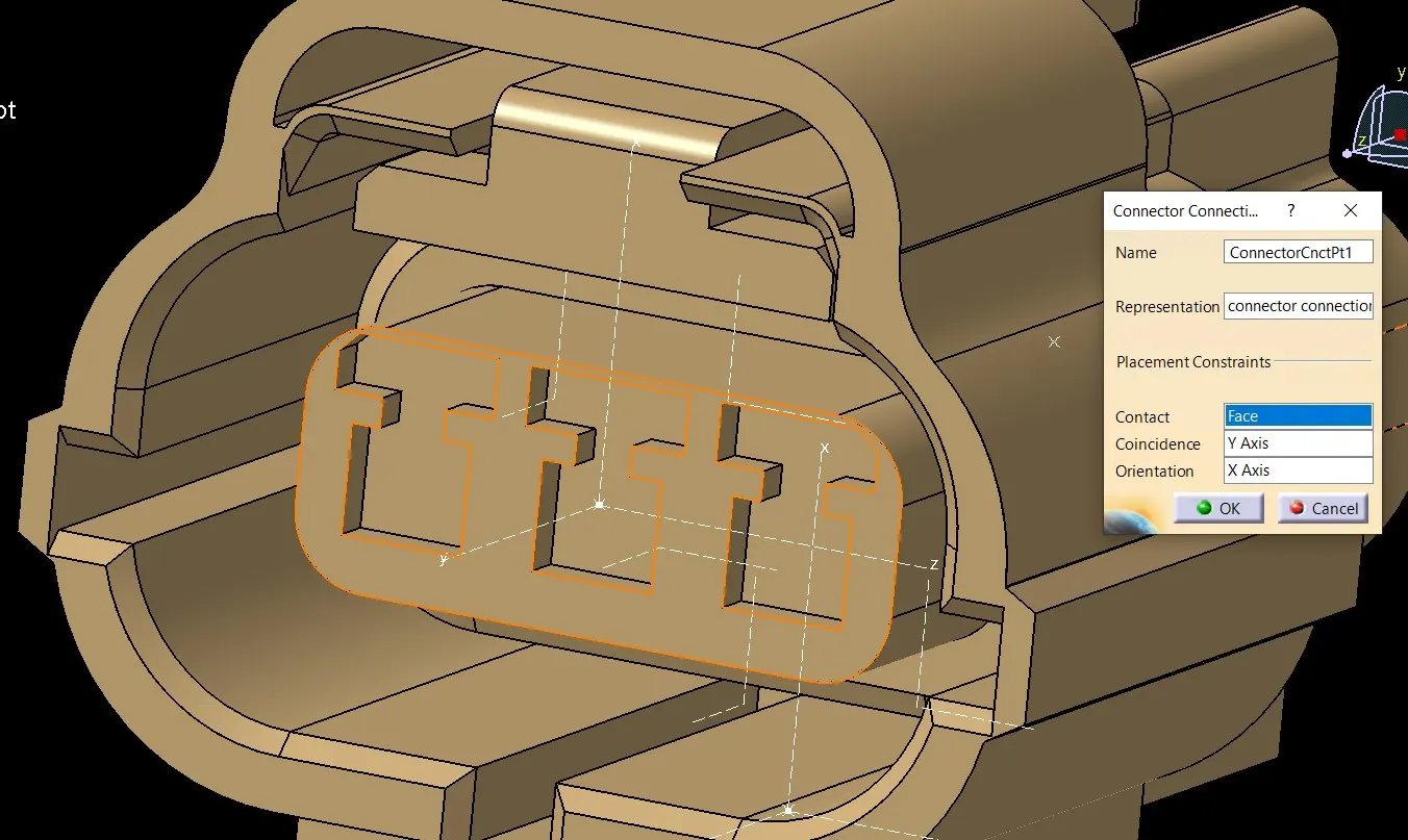
- create Connector connection point
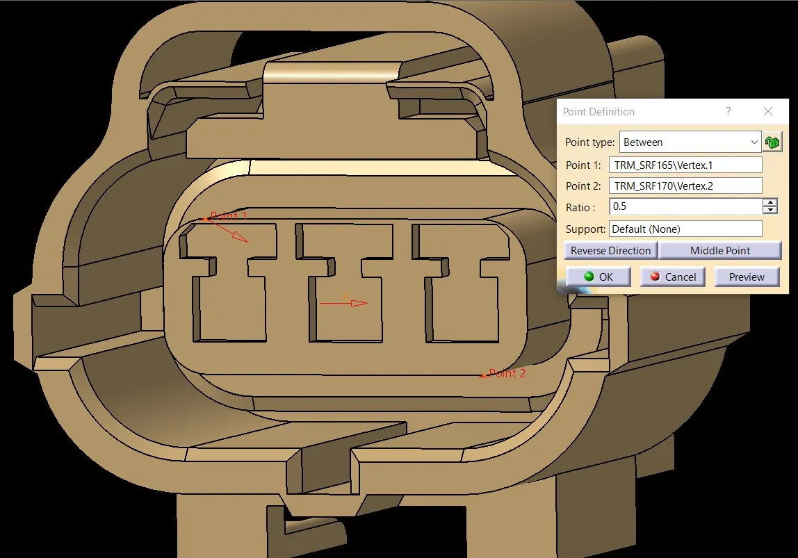
- create Connector connection axis system
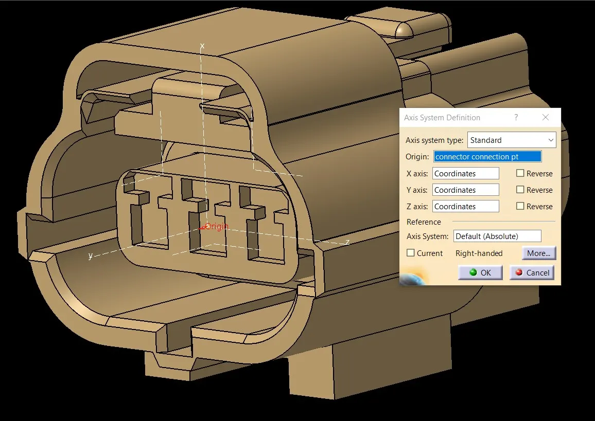
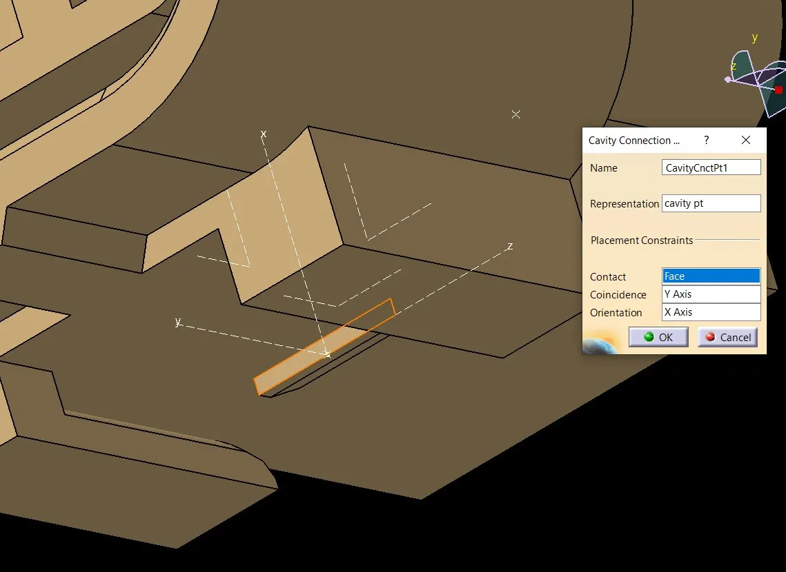
- create cavity connection point
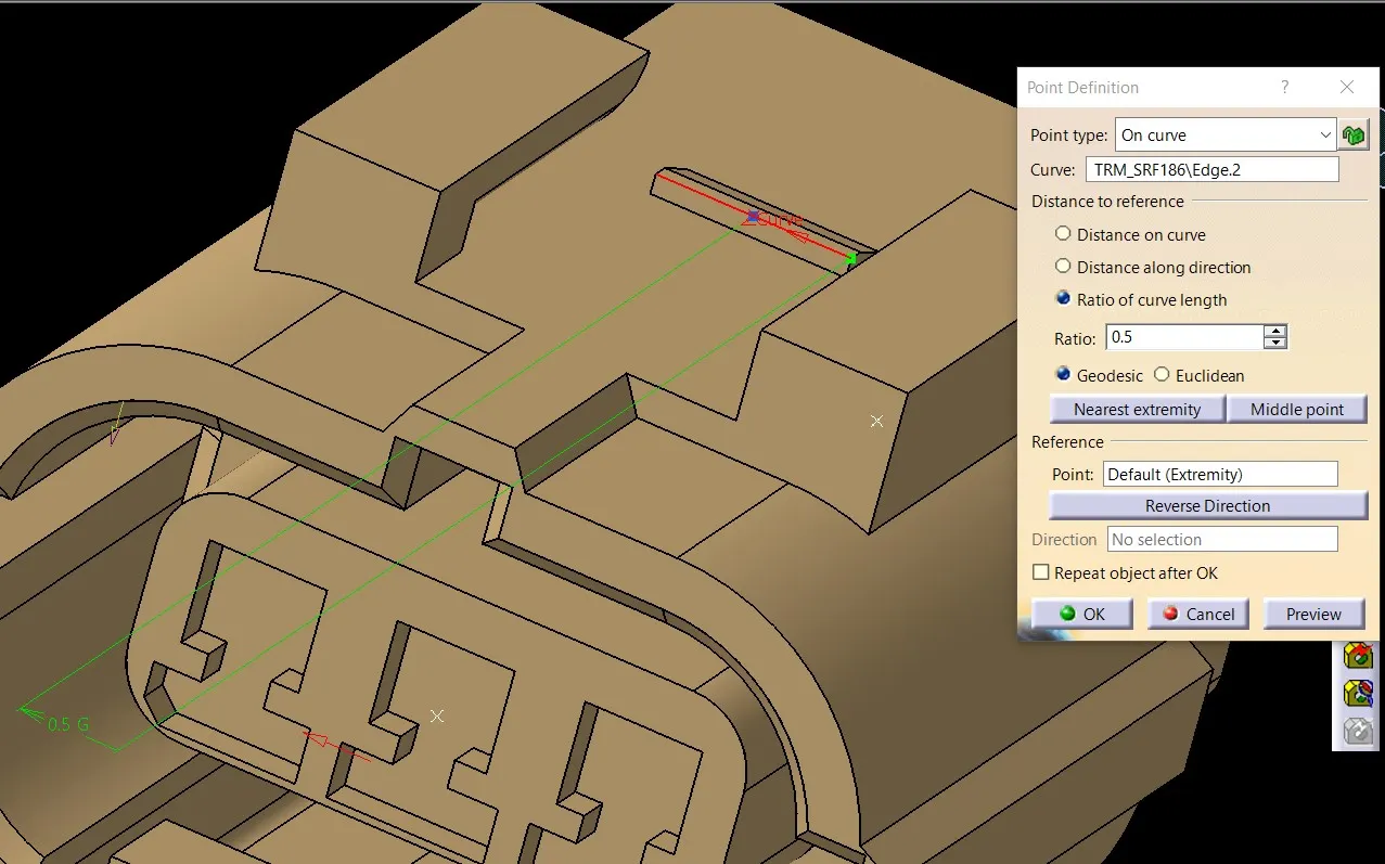
- create cavity connection axis system
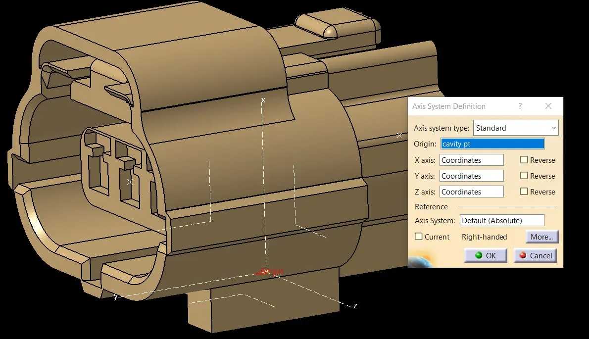
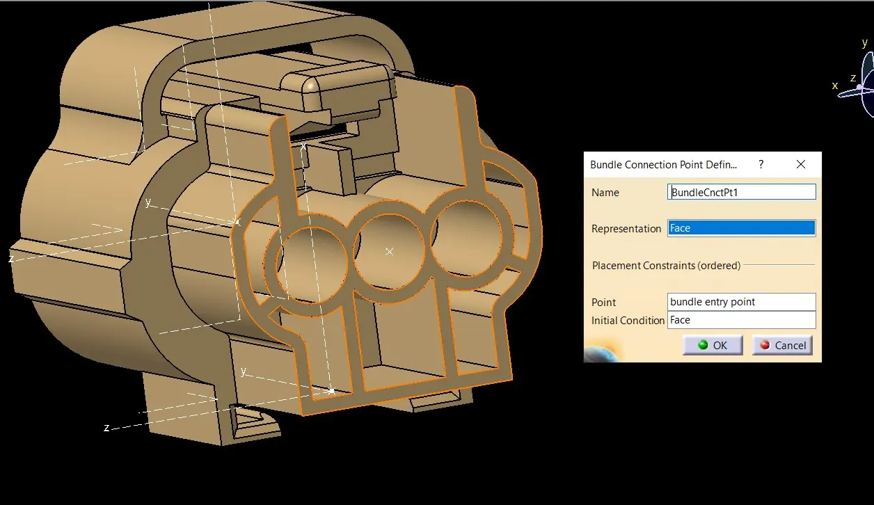
- create bundle entry point
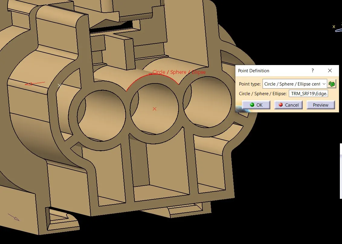
- Switch to Electric part design and define part as connector
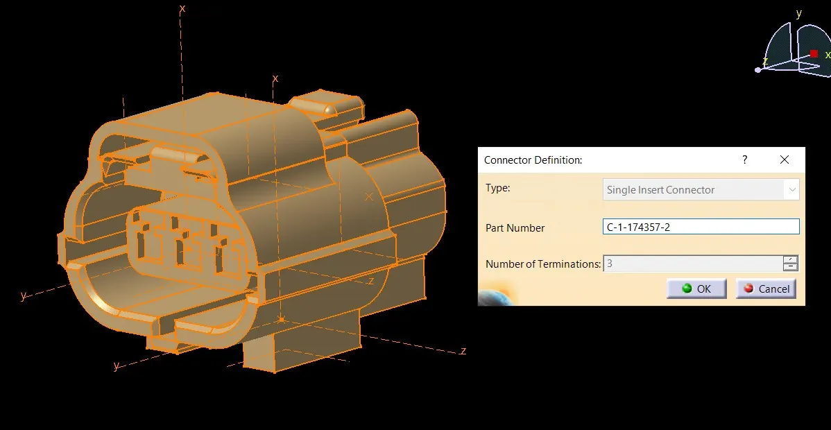
- Define Connector connection point
- cavity connection point
- bundle entry point
3. Tyco 85229-1
- create cavity connection point
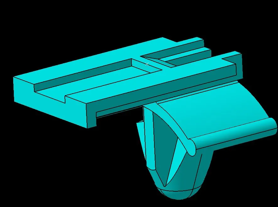
- create cavity connection axis system and orientation should be same as in connector
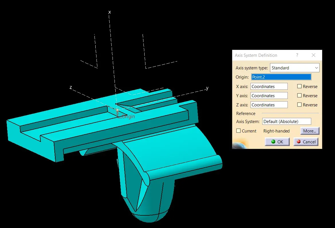
- Switch to Electric part design and define part as Mounting Equipment
- Define cavity connection point
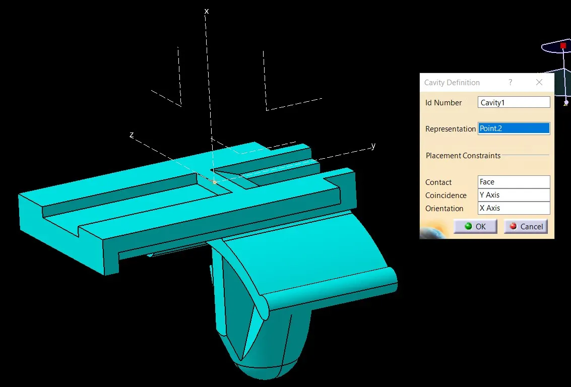
Elctrical Assembly Design
- Import Connector and mounting clip.
- Select Defing Eelectric connection
- select cavity and then connector.