Week 9 - Challenge 1 - Base Bracket Design
Base bracket
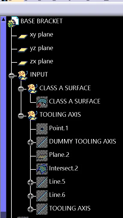
Before creating tooling axis make sure that class-A surface is properly joined and has no discontinuity with the help of boundary command or join command.
Creation of tooling axis
As we can see in given class a surface there are 2 holes and a flat surface first we create dummy tooling axis for that first consider X direction in this direction we cannot see one hole so we cannot take axis along this direction In Y direction we cannot see any holes so we cannot take this direction as well But in Z direction we can see 2 holes and flat surface so we can take this as our tooling axis direction
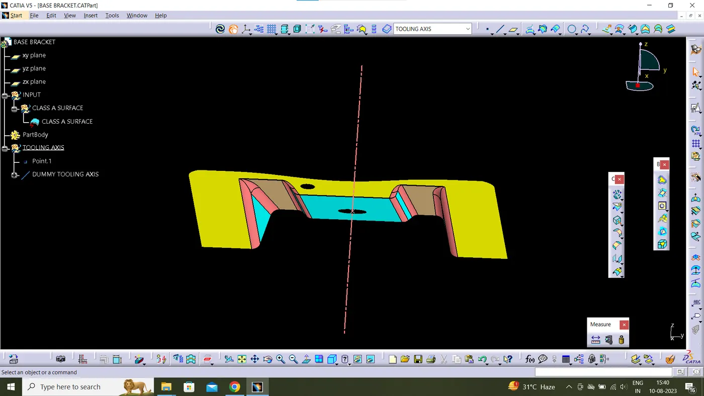
To create actual tooling axis Create an intersection of CLASS A surface with ZX plane and from the intersection create lines on drafted surfaces and then create a bisecting line as shown below
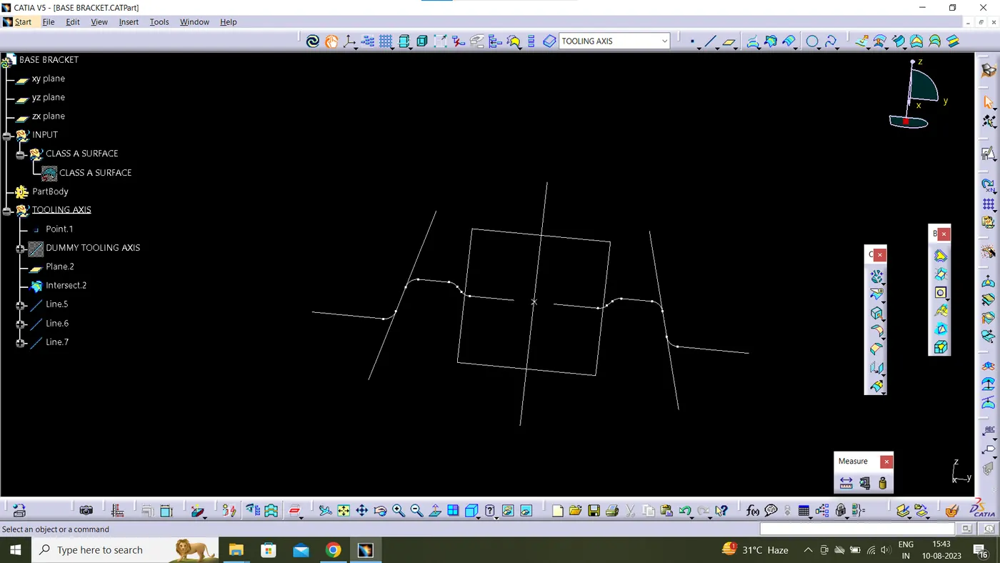
This bisecting line is the tooling axis
Draft analysis
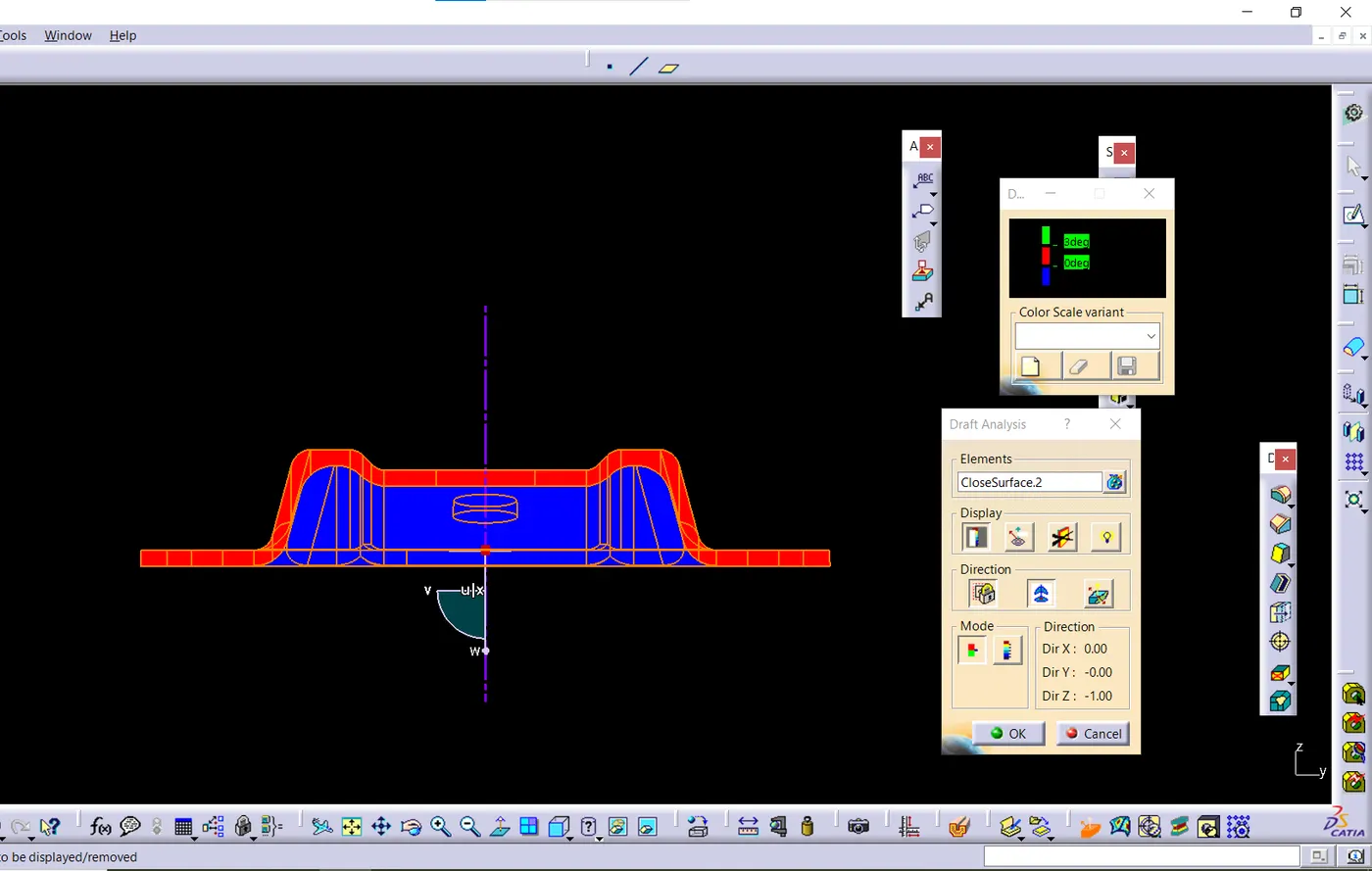
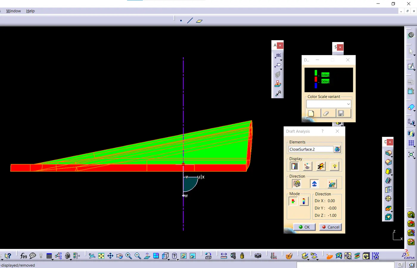
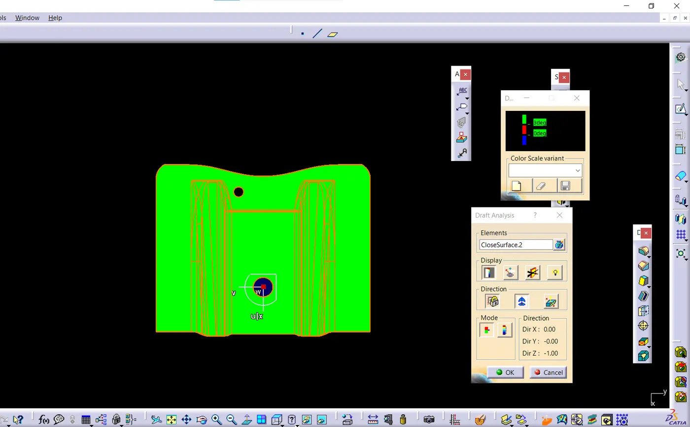
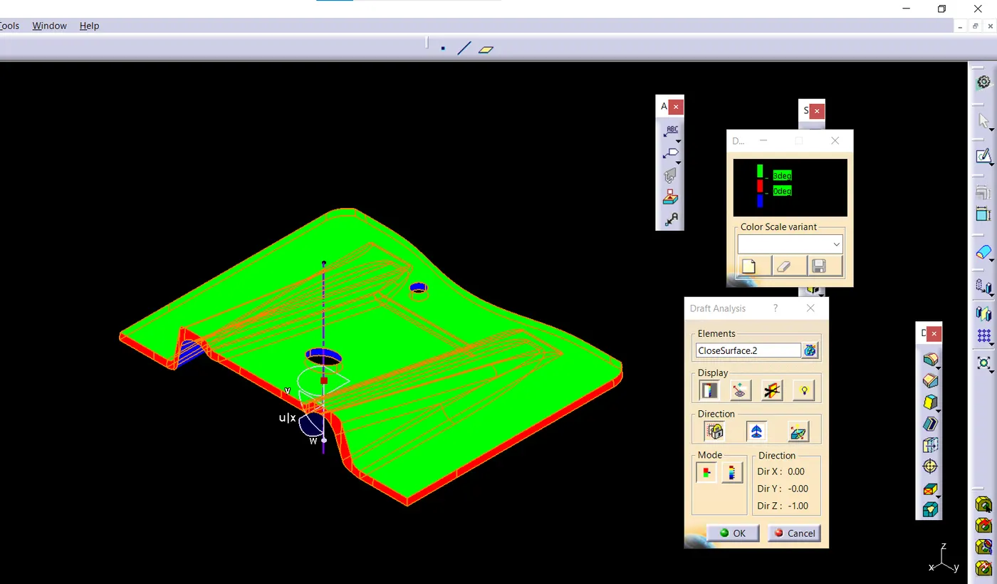
Open the draft analysis command and move the compass to coincide with tooling axis and lock the compass then select the component if it is green throughout that means draft analysis is correct
below images shows the process of draft analysis of class a surface
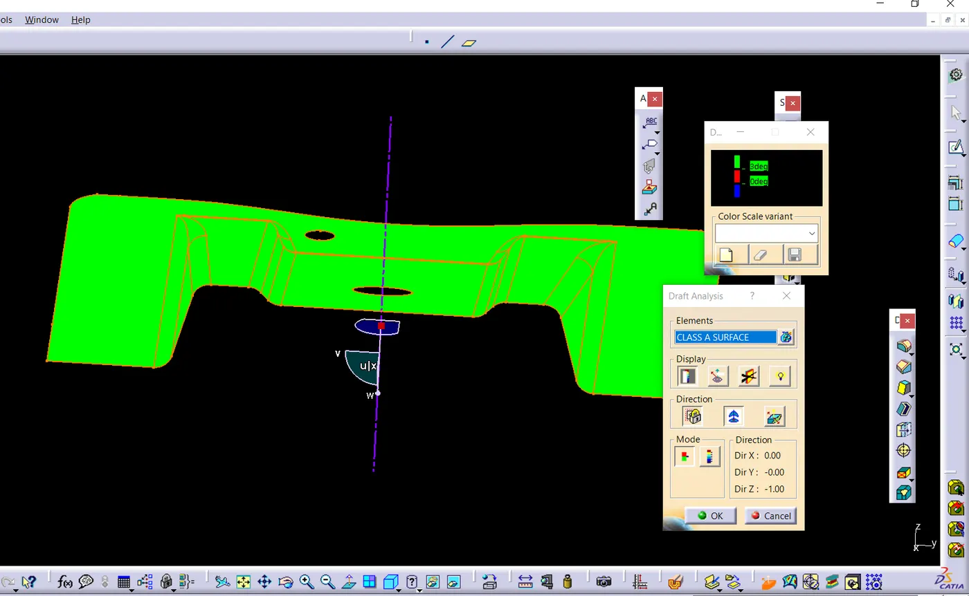
draft analysis of solid part
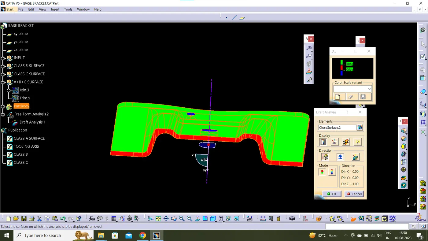
different views of solid part with draft analysis
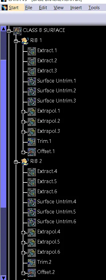
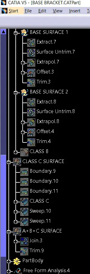
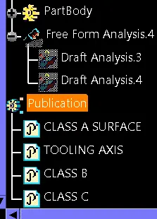
tree structure :