Week 9 - Challenge 3 - Bumper
BUMPER
Objective:- To create tooling axis of bumper plastic component and perform draft analysis on given class - A surface and final model.
CLASS A SURFACE
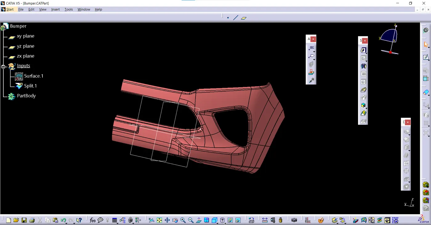
Creation of tooling axis:-
tooling direction basically define the direction of mold pulls apart To create the tooling axis first we have to check the best suitable direction for tooling by using the compass . the x direction is suitable for creating the tolling axis because in the x direction most of the surfaces are visible.
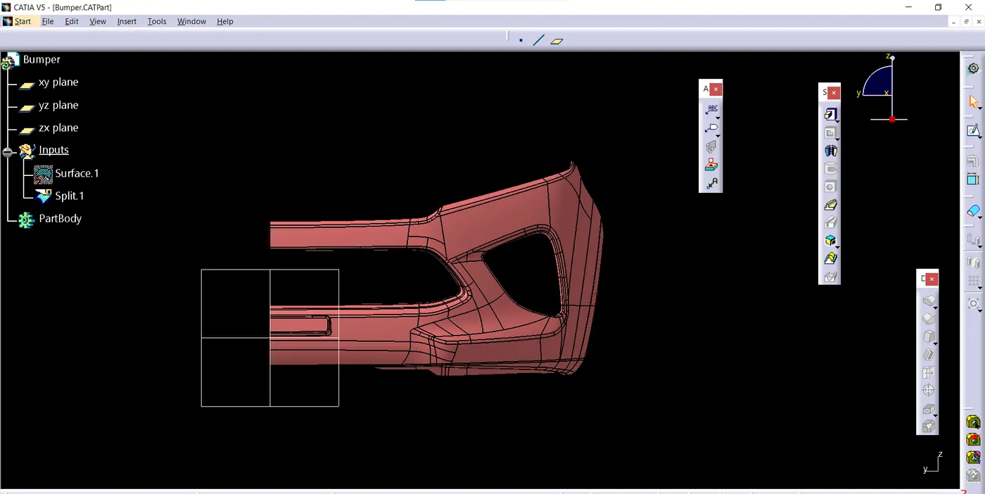
steps to create tooling axis
- create a point on curve as shown below
- make a line passing through that point in x direction this will be our tooling axis
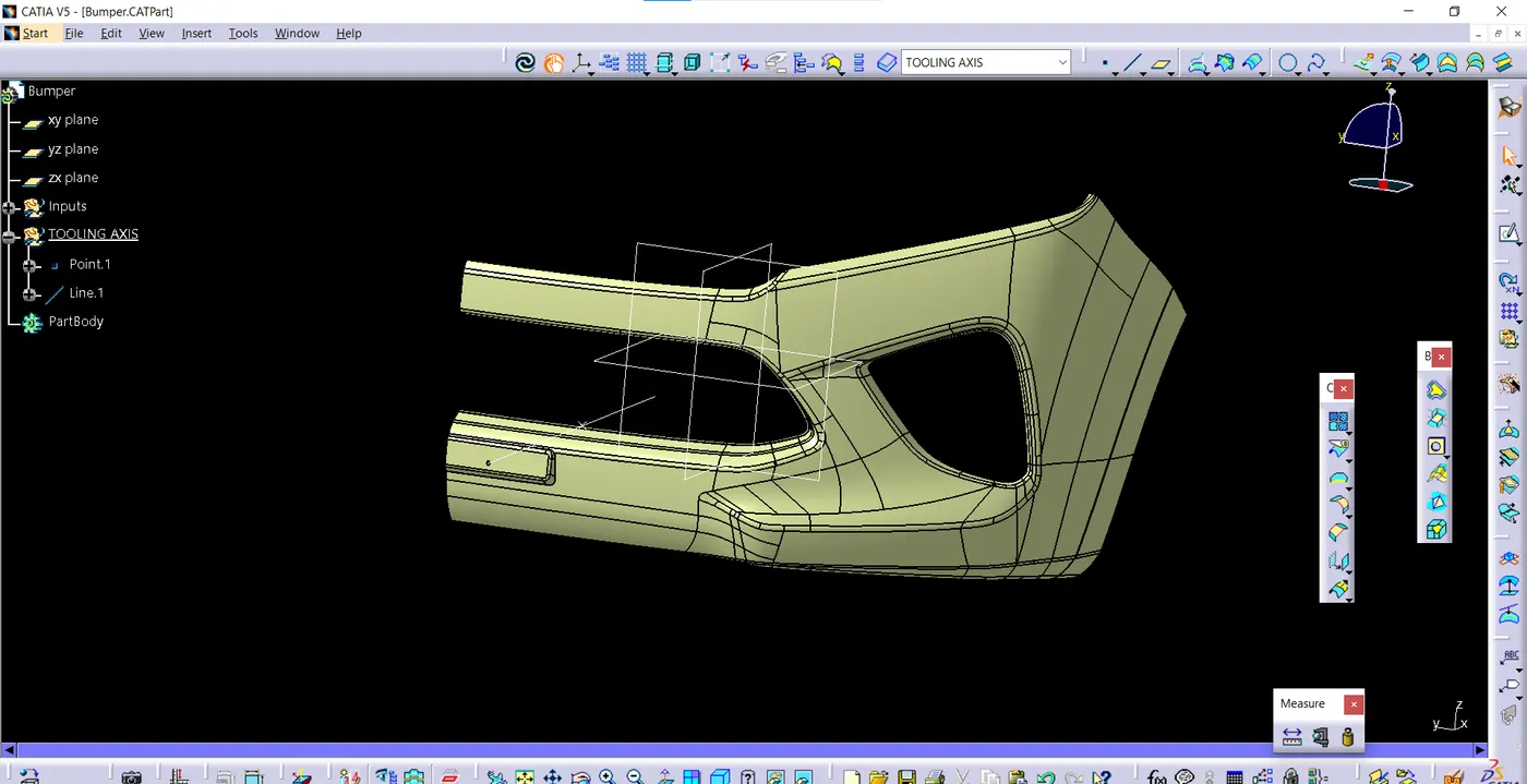
After creating a tooling axis we do the draft analysis. Before draft analysis we have to make sure that in the view mode it is selected for the materials.
Draft analysis :-
The Draft Analysis command enables you to detect if the part you drafted will be easily removed
After selecting the feature draft analysis tool we drag the compass from its position to the tool axis. Then lock the compass. After that select anywhere on the component and it will give you the result
give the draft angle 3 degree.
the surface is in green colour (means draft angle > 3 degree) is right. And where the colour is blue mean draft angle is between 3 degree to 0 degree . If there is red colour zone then it means draft angle is less than 0 degree. Then you will have to create tooling axis by another way.
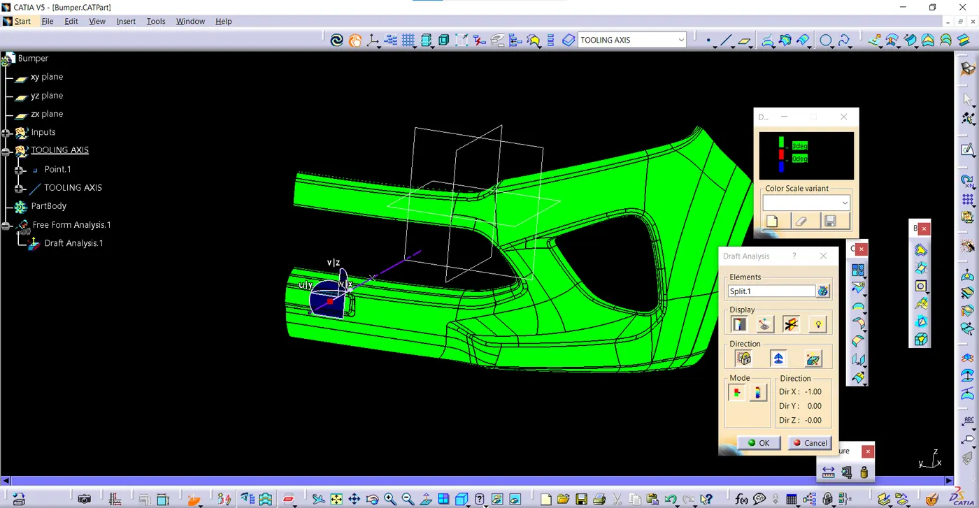
DRAFT ANALYSIS OF CLASS A SURFACE
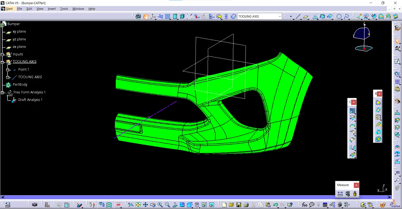
DRAFT ANALYSIS OF SOLID PART
- Go to the Insert menu and select the Analysis option.
- Select Feature Draft Analysis.
- Select the Material option and select the surface.
- Drag the compass and place it on the tooling axis.
- click on the surface and see that the surface is within the permissible limit of the draft values.
- Here i change the draft anagle to 2.5 to make sure all surfaces clear draft analysis
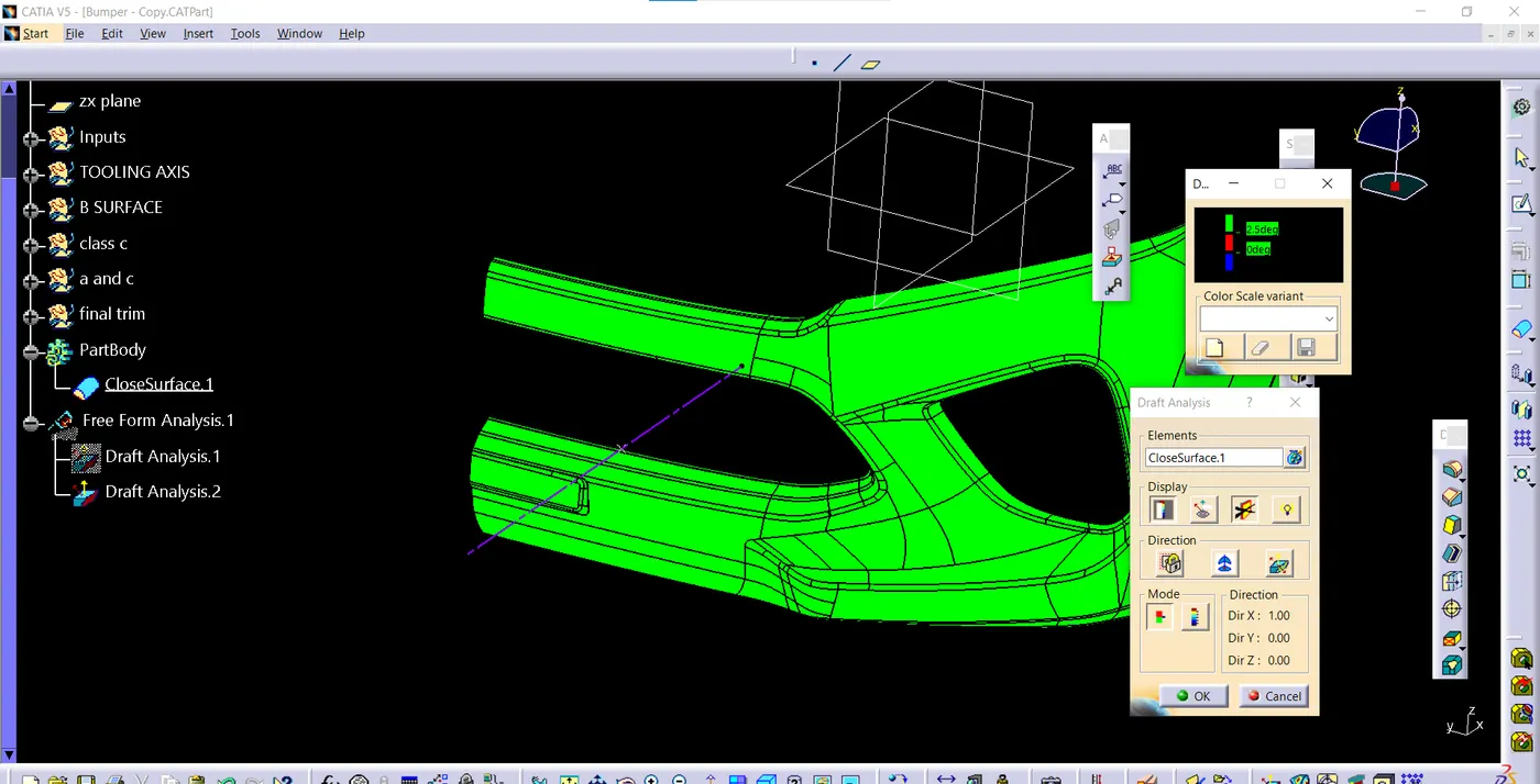
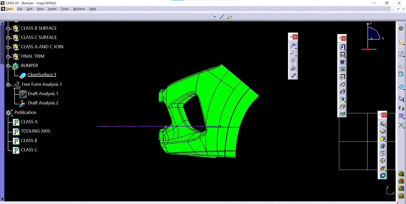
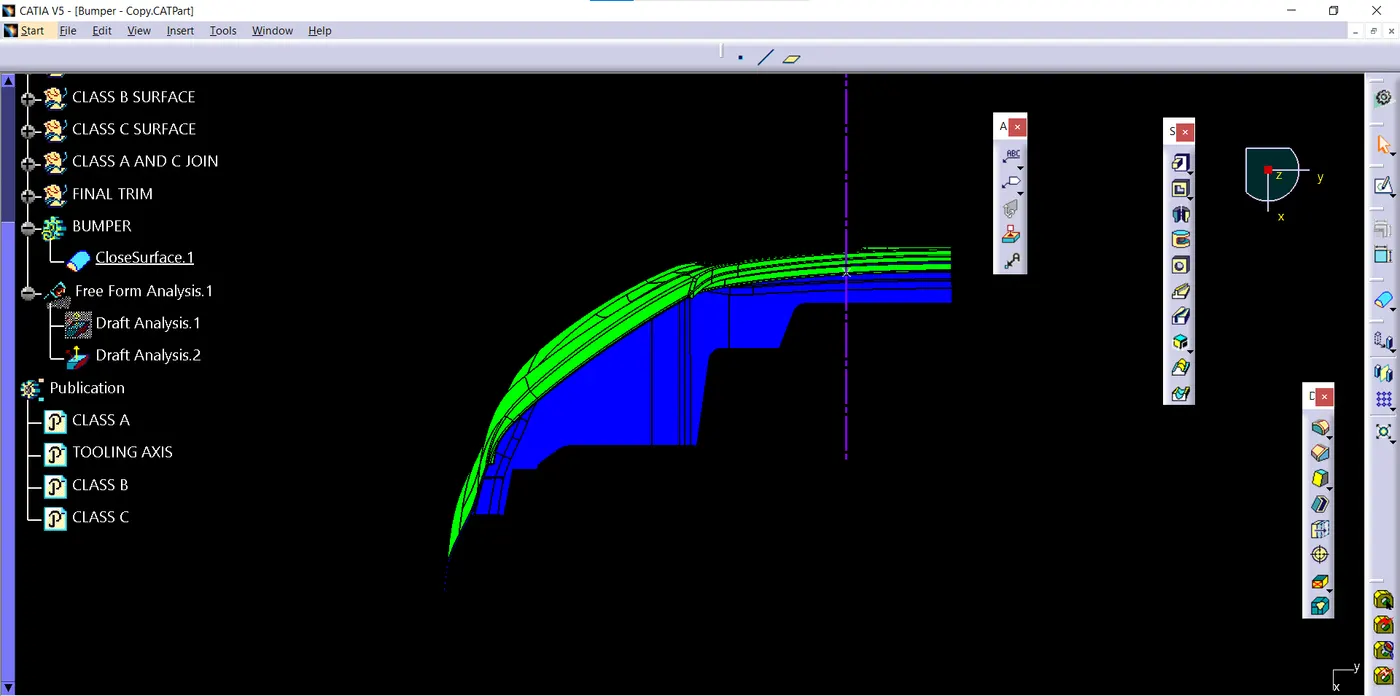
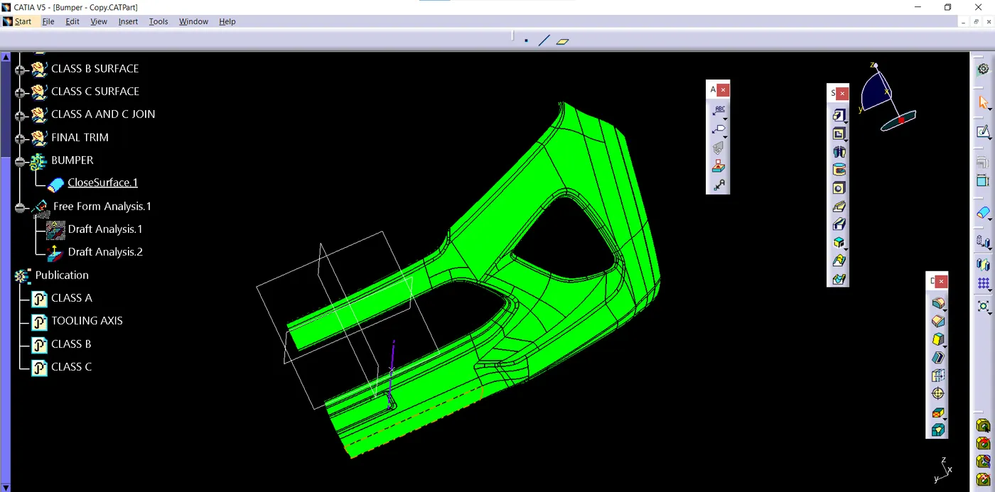
DIFFERENT VIEWS
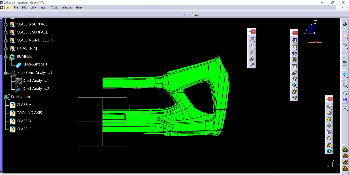
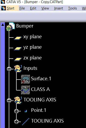
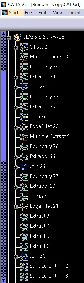
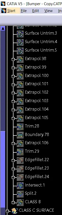
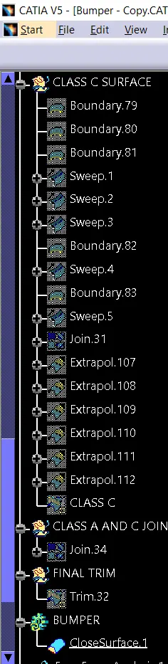
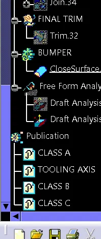
TREE STRUCTURE