Week 9 - Challenge 2 - Switch Bezel Design
Switch bezel
Objective:-
<!-- [if !supportLists]-->· <!--[endif]-->To create tooling axis and perform draft analysis on given class - A surface and final component
Given A-Class Surface
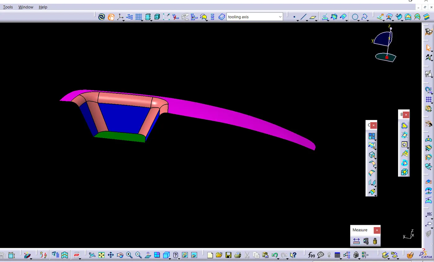
Creation of tooling axis:- bisecting method
- Extract base surface and create a point on that surface
- first we create LINE ALONG Y DIRECTION By use of command Create 3D element to create part profile in 2D Then with the help of the below shown inclined lines two lines are created
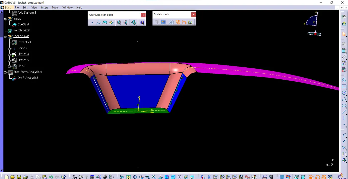
- Create a bisecting line by above two lines
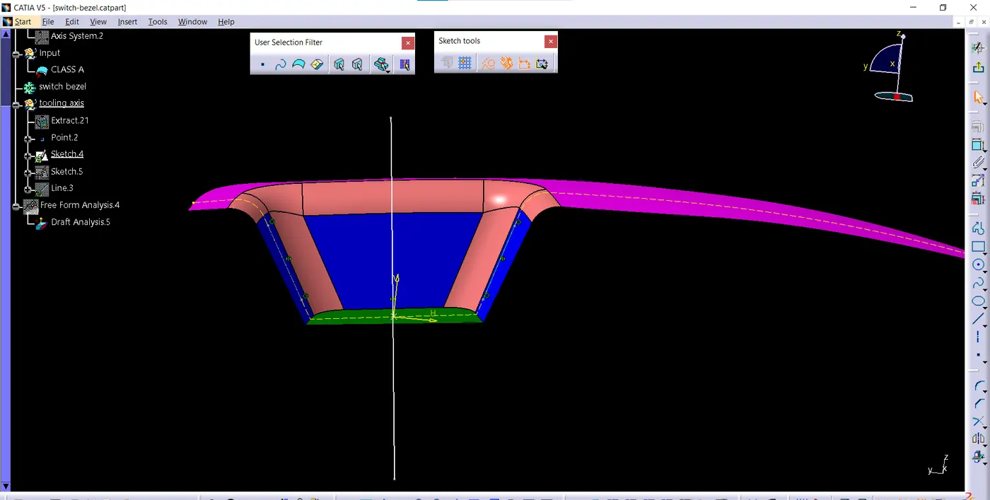
- now we create LINE ALONG X DIRECTION and for that create a line passing through point as shown below
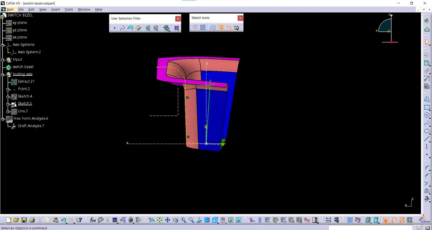
- create bisecting line with the help of above two lines along x and y direction this bisecting line will be the tooling axis
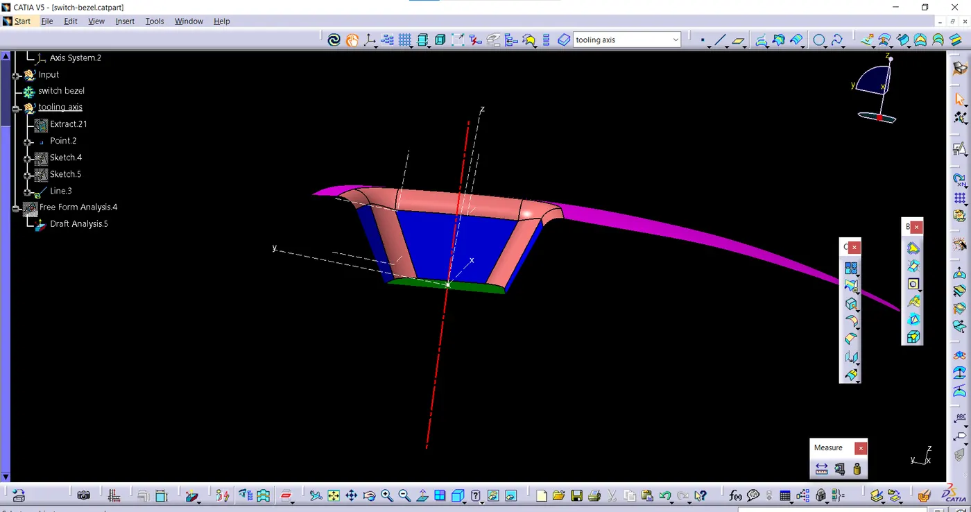
Draft analysis of class A surface:-
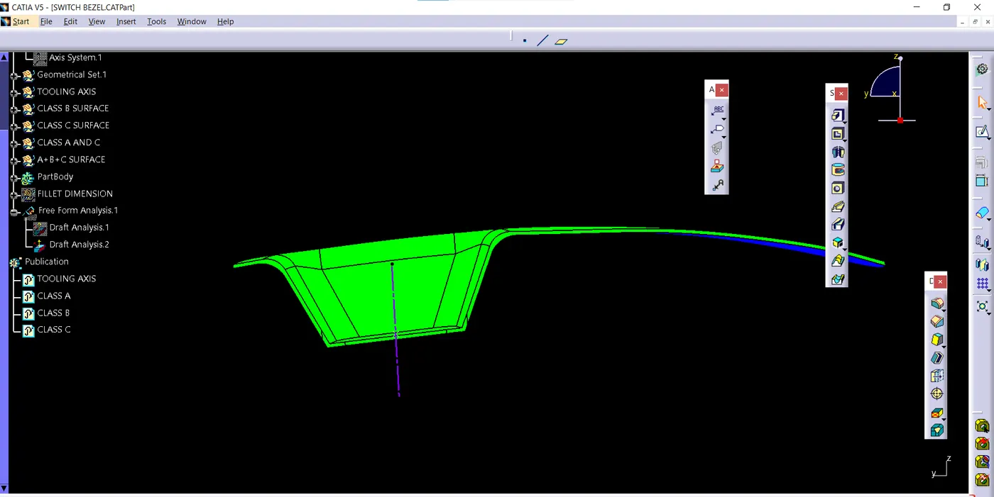
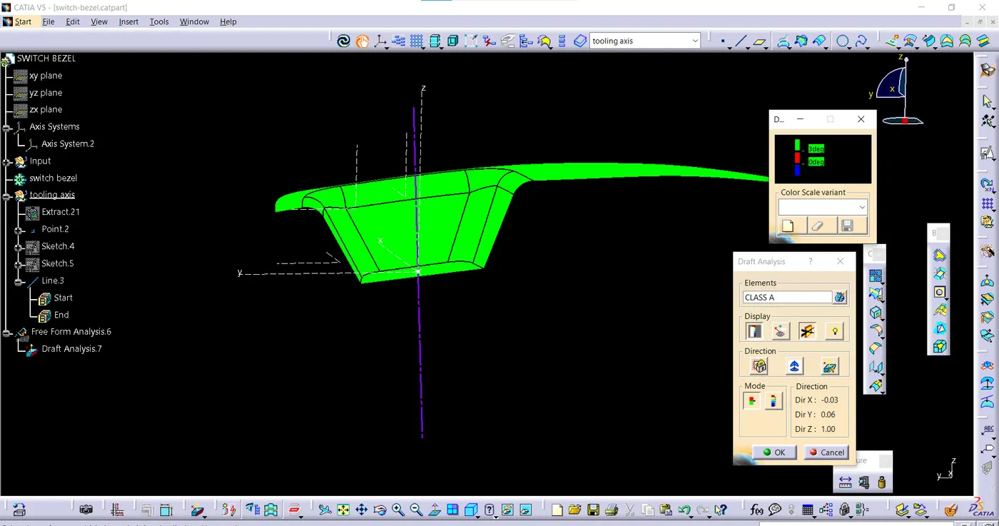
Open the draft analysis command and move the compass to coincide with tooling axis and lock the compass then select the component if it is green throughout that means draft analysis is correct
below images shows the process of draft analysis of class a surface
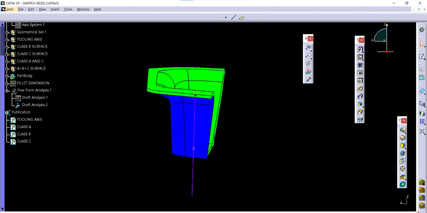
draft analysis of solid part:-
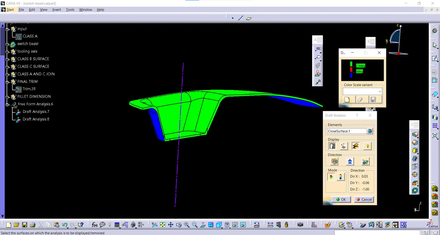
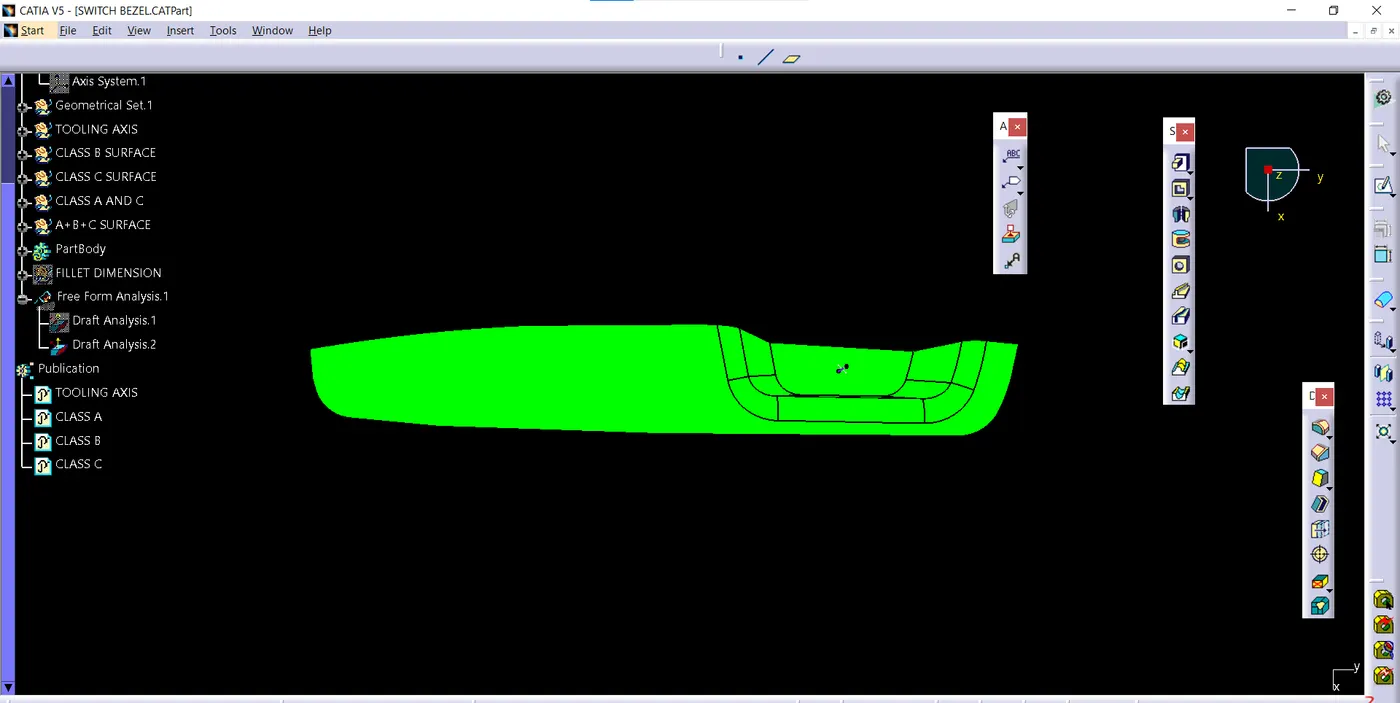
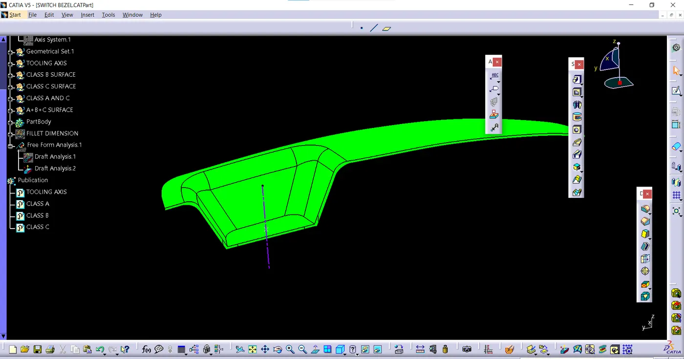
different view of switch bezel:-