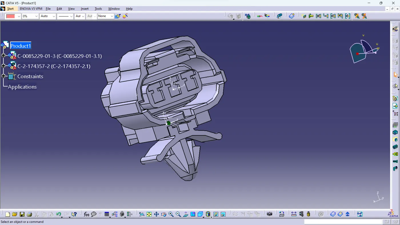
Wiring harness design in CATIA V5 - 3D modeling Week 2 Challenge
Report on Electrical Connectors and Connector Clips Design
1. Introduction:
This comprehensive report outlines the step-by-step design process for three electrical connectors—Deutsch DT06-08SA, Tyco 174357-2, and Tyco 85229-1. The design involves creating bundle entry points, connector connection points, a cavity connection point for a clip mount, and defined mounting equipment using the Electrical Part Design Workbench.
2. Creating Connectors - Deutsch DT06-08SA:
- Open the Part Design Workbench.
- Create a bundle entry point for the connector.
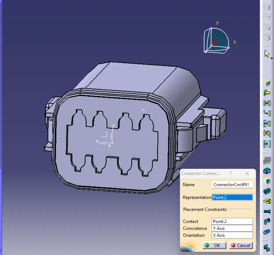
- Create a point with an axis system for the connector connection point.
- Switch to the Electrical Part Design Workbench.
- Define the connector as having 8 terminations.
- Specify the bundle connection point and the connector connection point.
- Ensure coincidence by selecting the y-axis for position and the x-axis for orientation.
-
3. Creating Connectors - Tyco 174357-2:
- Open the Part Design Workbench.
- Create a bundle entry point for the connector.
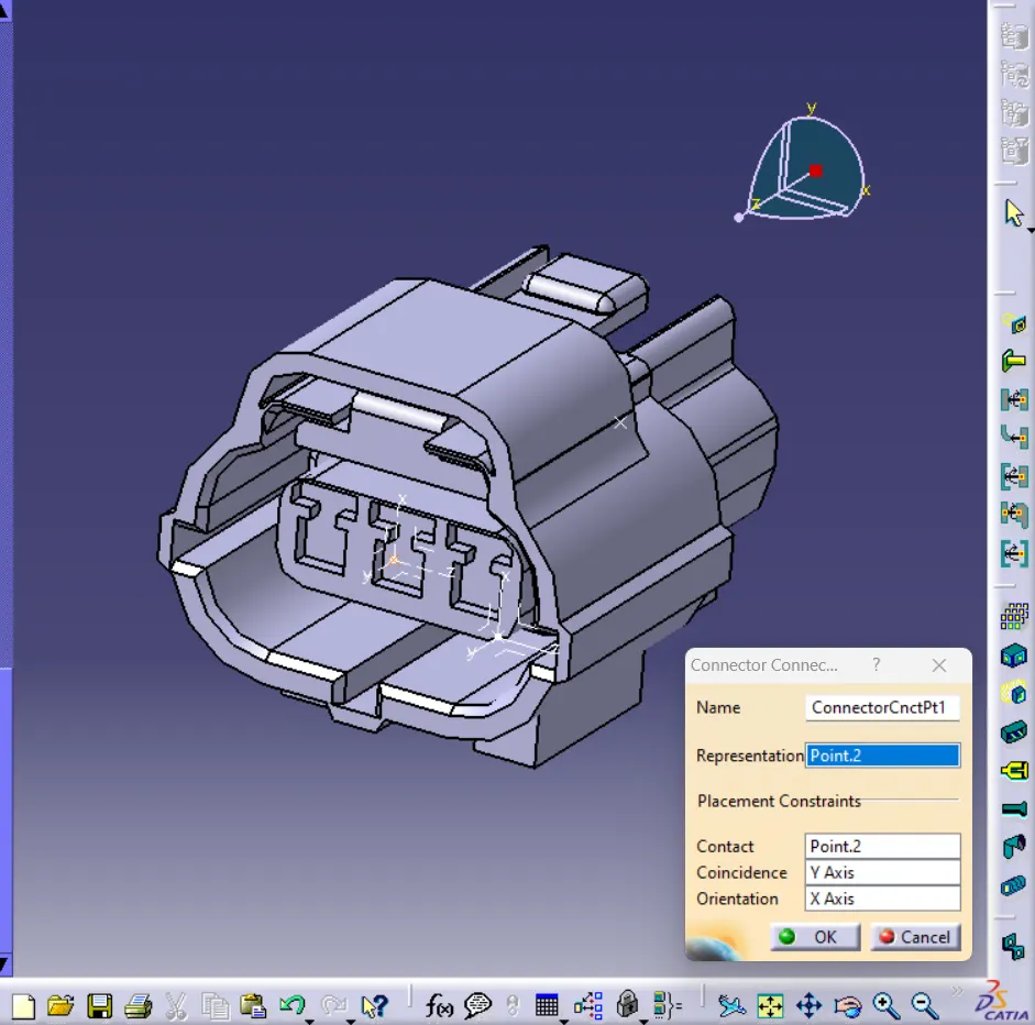
- Create a point with an axis system for the connector connection point.
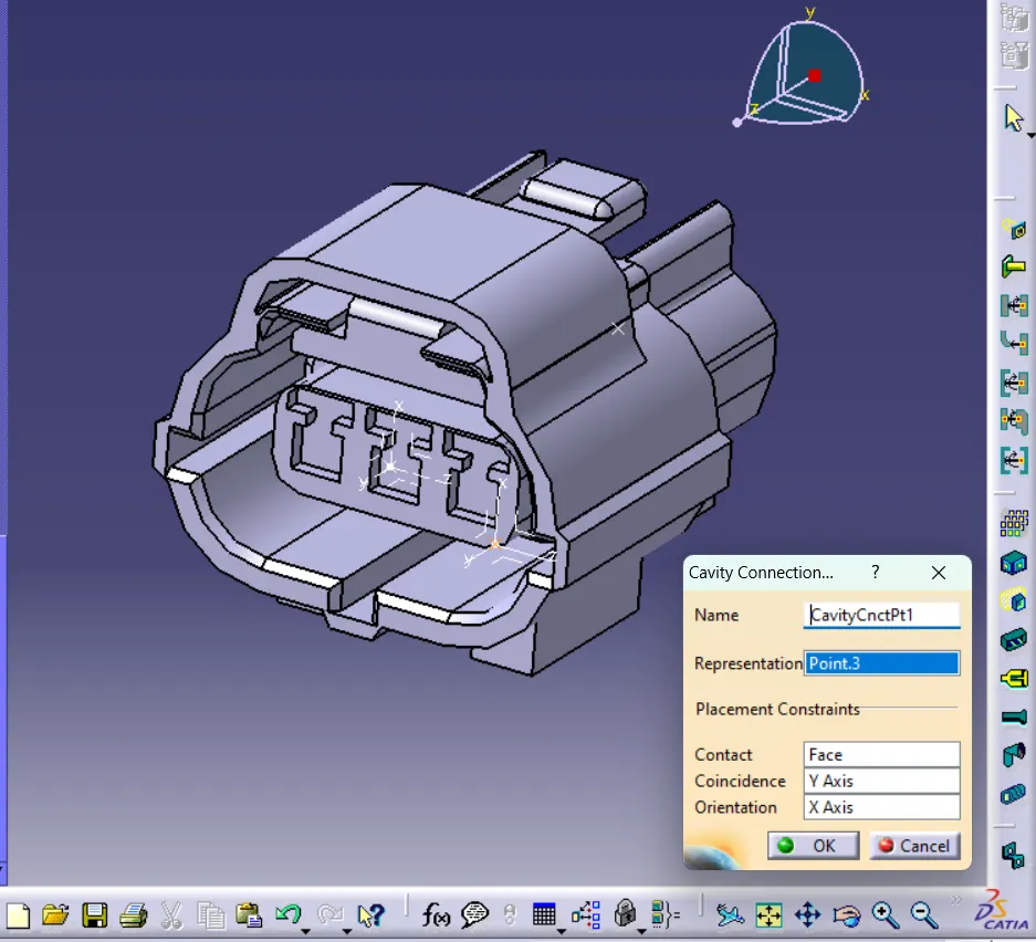
- Create a cavity connection point for the clip mount.
- Switch to the Electrical Part Design Workbench.
- Define the connector as having 6 terminations.
- Specify the bundle connection point, connector connection point, and cavity connection point.
- Ensure coincidence by selecting the y-axis for position and the x-axis for orientation.
-
4. Mounting Equipment Properties - Tyco 85229-1:
- Define the properties of the mounting equipment associated with Tyco 85229-1, considering the defined cavity.