Wiring harness design in CATIA V5 - 3D modeling Week 2 Challenge
Wiring harness design in CATIA V5 - 3D modeling Week 2 Challenge
Aim:
Download following connectors & Connector clip cad data from given link & define it as Electrical Connector using Electrical Part design Workbench. Define all the necessary properties to Connectors & Clip
Connector:
A connector is a device (or more precisely, a mating pair of devices, often a plug and a socket) for connecting together two or more wires, cables, or hoses, allowing electricity or fluid to flow but also allowing easy disconnection and reconnection when necessary.
Mounting Clips:
Mounting Clips are used for supporting conduits. These clips are made of High-Quality Impact Resistant Polyamide. The mounting clips are stackable and are fixed with the help of screws onto the panel or equipment surface.
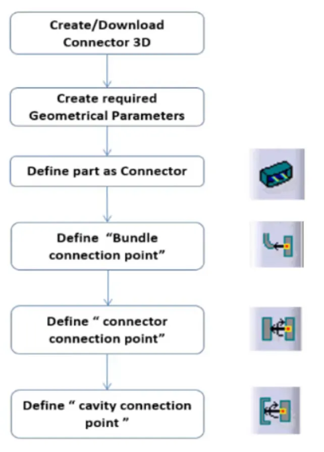
Connector Definition Flow Chart:
Parameters required:
Geometry Parameters:
Points - connector connecting point, bundle connecting point
Coordinate System (Axis) - for defining coincidence direction and locking direction
Connector Connection Points - This point is used for the connection of one connector to another connector.
Bundle Connecting Point - This point defines where the harness bundle segment point will end when routed to the electrical connector.
Cavity Connection Point (Optional) - This point is used to define the connection of a connector to a connector clip. This only applies to connectors that have the mounting feature for a connector clip.
Connectors 1: Deutsch DT06 – 08SA
- Import the downloaded step or igs file into the CATIA mechanical
- part workbench and save as cad part.
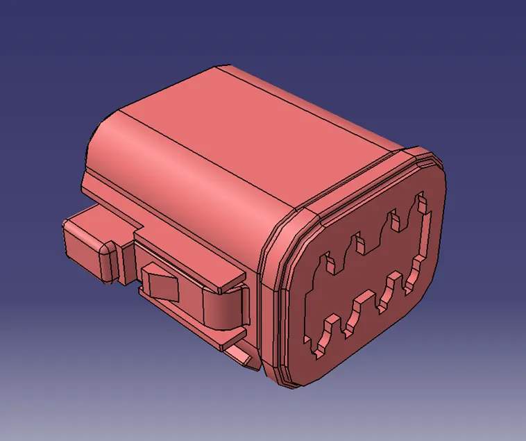
- Define the Bundle Entry Point.
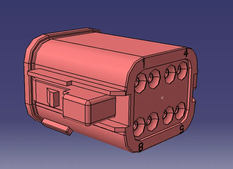
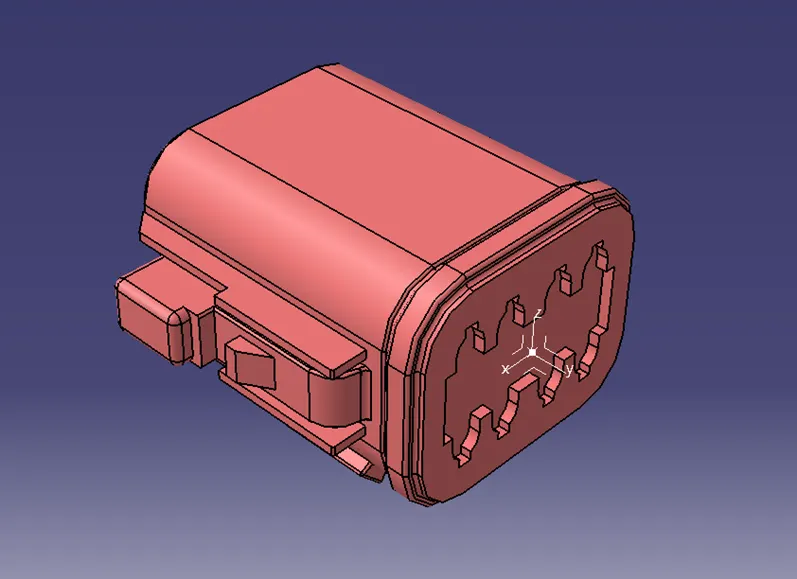
- Define the Connector Connection Point.
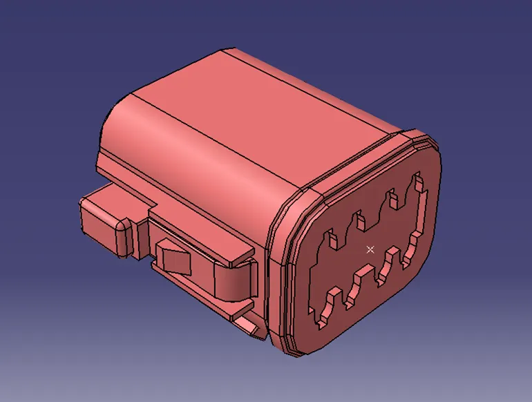
- Define Connector Connection Axis. Y-Axis should face the other mating part/direction and X-Axis should face the lock.
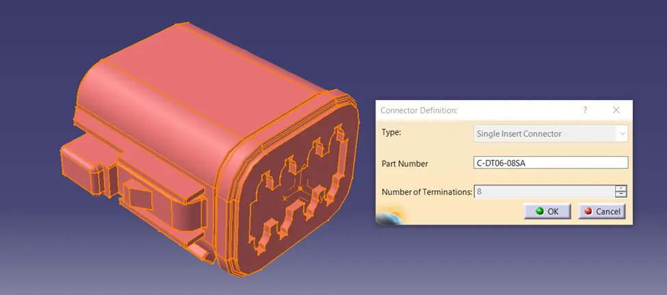
- Now switch to the Electrical Part Design Workbench and define the connector using Define Connector Command with Name and No. of Terminals.
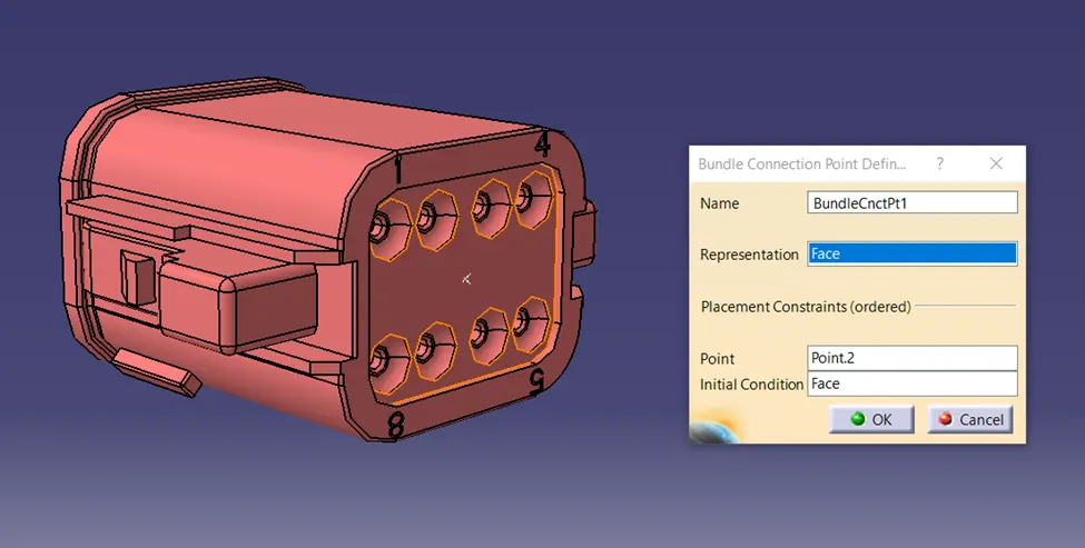
- Define the Bundle Connection Point. Face as Representation, Bundle Entry Point as Point, and Same face as Representation for Initial Condition.
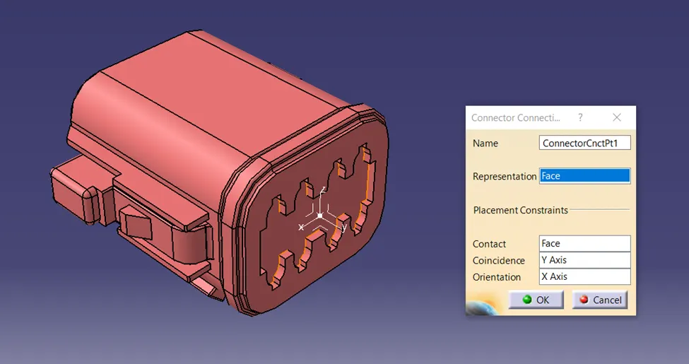
- Define the Connector Connection Point. Connector Connection Point as Representation, Mating Face as Contact, Y-axis as Coincidence, and X-Axis as Orientation.
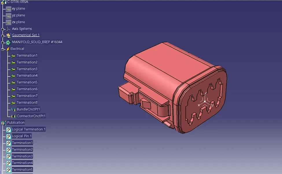
Connectors 2: Tyco 174357-2
- Follow the same steps as we did in Connector 1. Define Bundle Entry Point, Connector Connection Point, and Connector Connection Axis (Y-Axis facing mating part/direction & X-Axis facing lock).
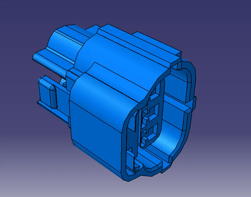
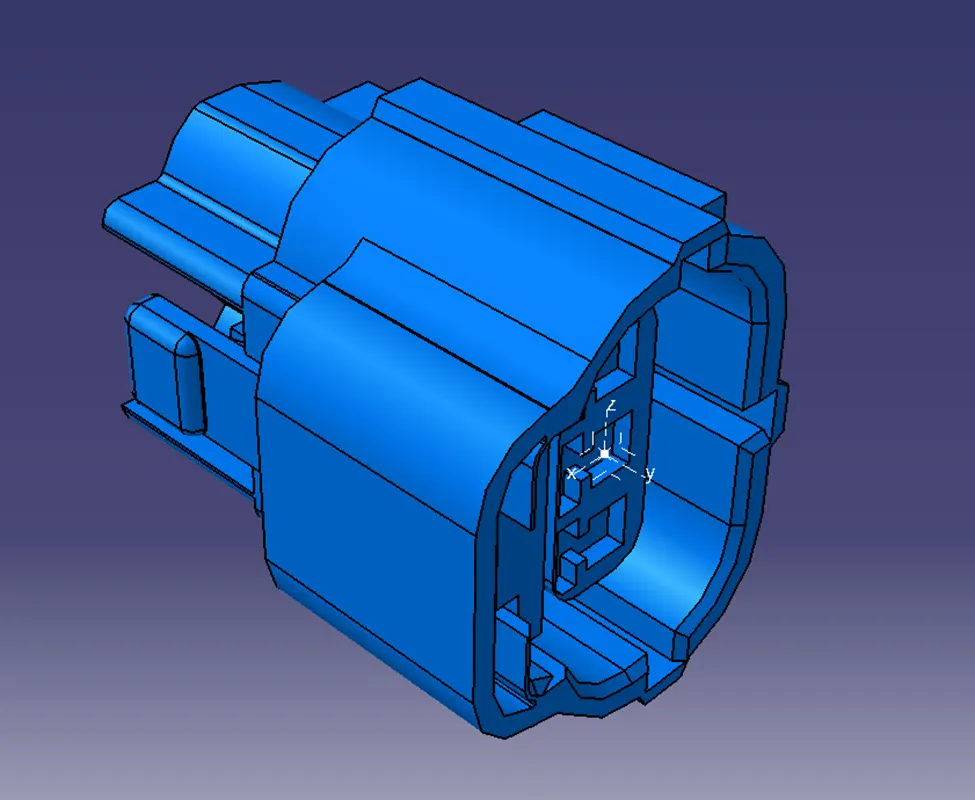
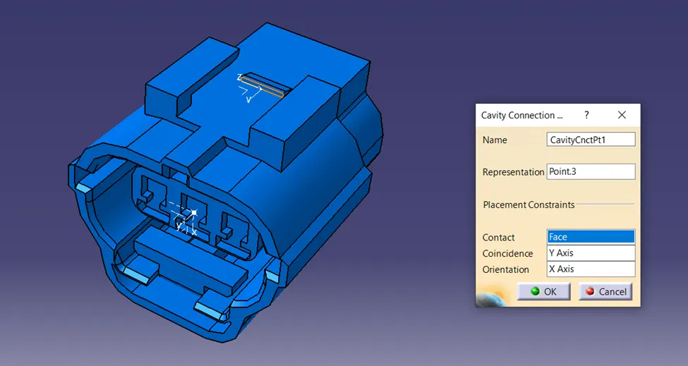
- This connector has Clip/Mounting Cavity. So, define the Clip/Mounting Cavity Point and Clip/Mounting Cavity Axis (Y-Axis facing mating part/direction & X-Axis facing lock).
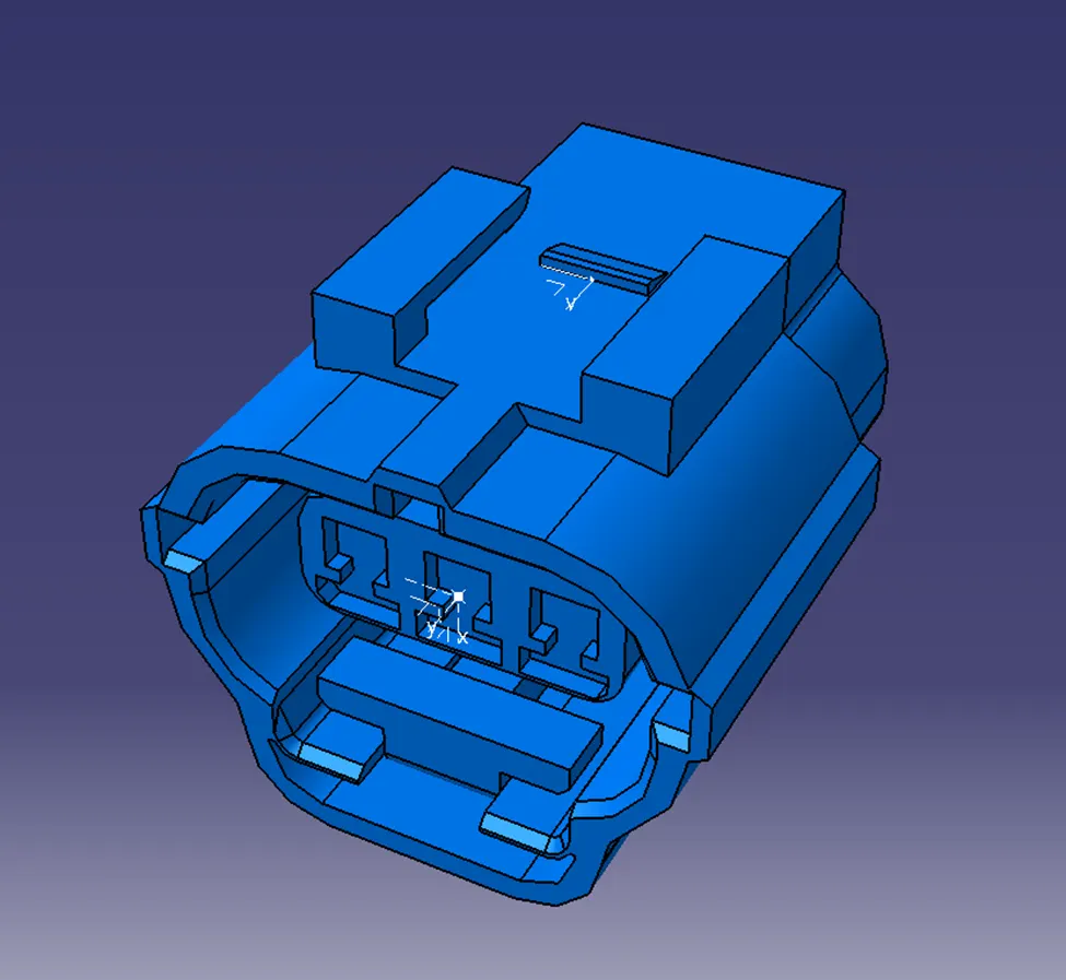
- Now we follow the same steps as we did in Connector 1. Define as a connector, Bundle Connection Point, and Connector Connection Point).
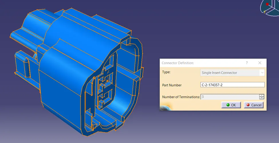
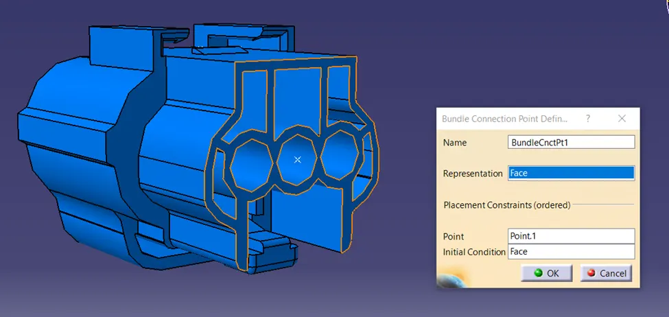
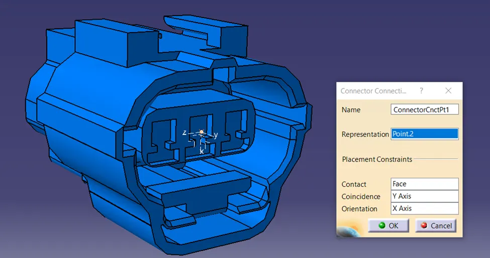
- Define the Connector Clip/Mounting Cavity. Connector Clip/Mounting Point as Representation, Mating Face as Contact, Y-axis as Coincidence, and X-Axis as Orientation.
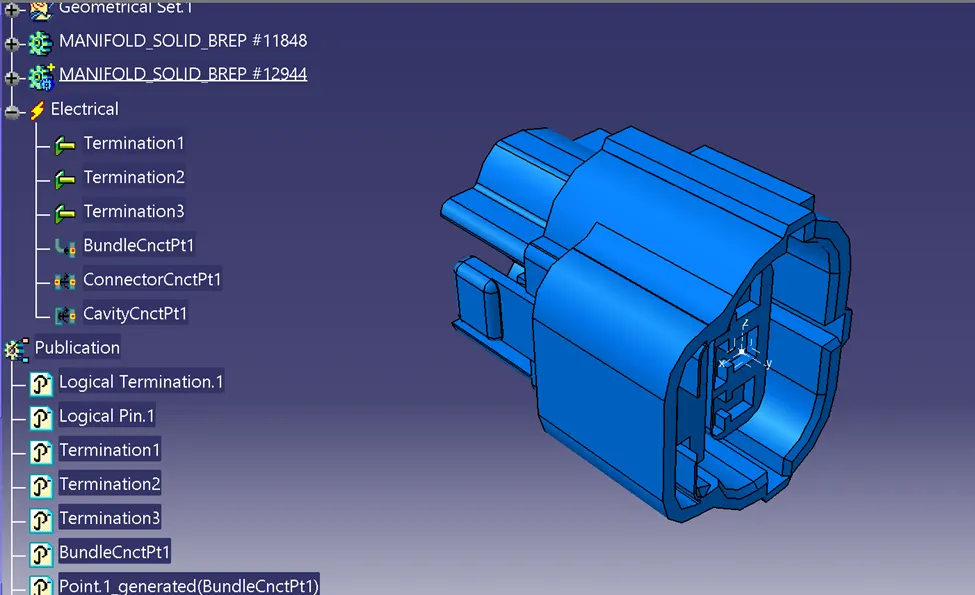
CONNECTOR CLIP: Tyco 85229-1
- Import the downloaded step or igs file into the CATIA mechanical part workbench.
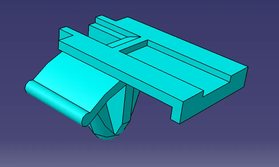
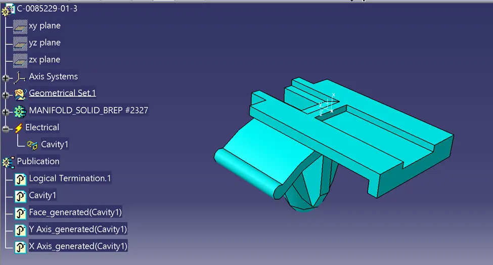
- Define the Clip/Mounting Cavity Point and Clip/Mounting Cavity Axis (Y-Axis facing mating part/direction & X-Axis facing lock). The Cavity Axis should be similar to the Connector Cavity Axis for the correct assembly of the par
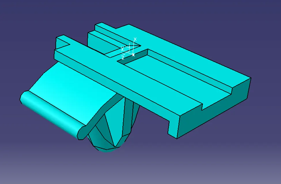
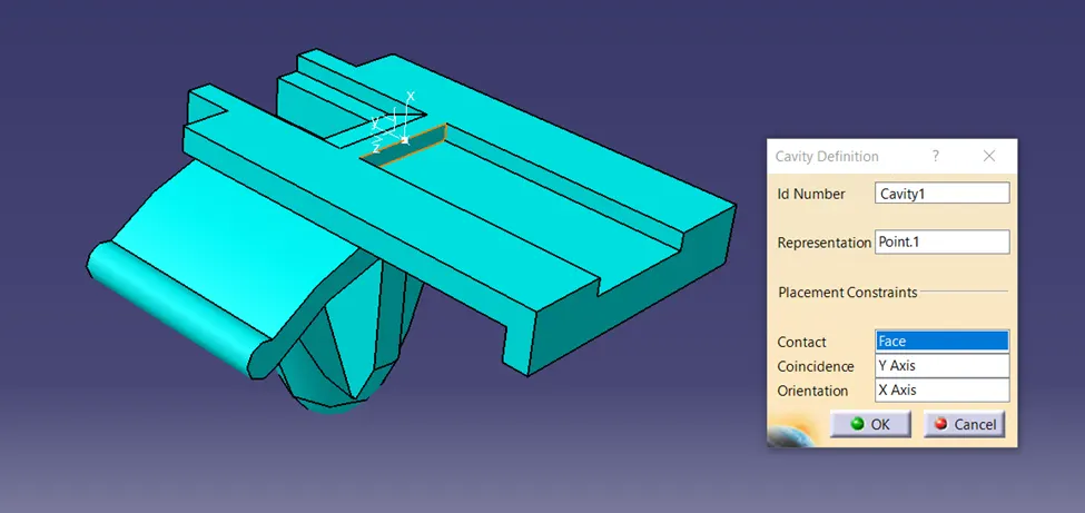
- Define the Mounting clip as Cavity. Connector Cavity Point as Representation, Mating Face as Contact, Y-axis as Coincidence, and X-Axis as Orientation.
CONNECTOR AND MOUNTING CLIP ASSEMBLY
- Import both the parts in the Electrical Assembly Design workbench and align them properly.
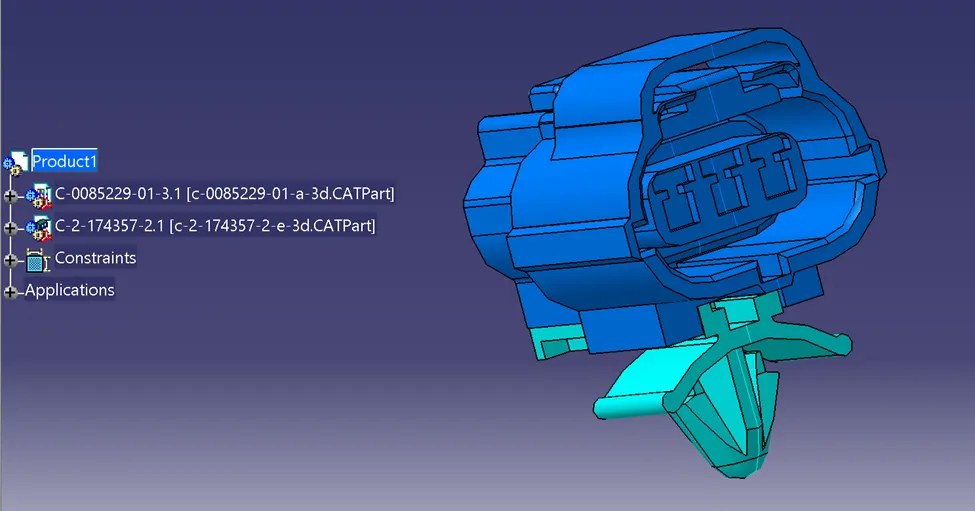
- Using the Connect Electrical Devices command First select the Mounting Clip and then Cavity Connection Point will show on the Connector in green color automatically.
- Select the Highlighted green point and the parts will assemble together automatically in the correct position with respect to the defined Connector Cavity Axis on both parts.