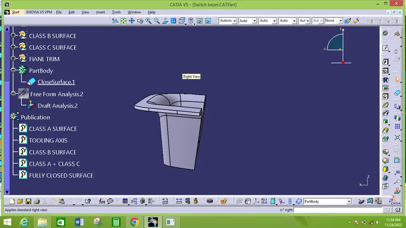
Week 8 - Challenge 2 - Switch Bezel Design
Switch Bezel Design
Aim:
To create a Base Bracket Plastic Component through a given Class A Surface and perform Draft Analysis on the final plastic component.
- Creation of Tooling Axis.
- Creation of Class B and Class C surface.
- Creating a solid part out of surface modelling.
- Draft Analysis of Class A surface and final plastic component.
Input:
The following surface is given as the input for the component creation.
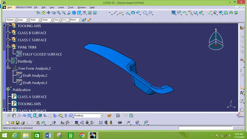
Input checking:
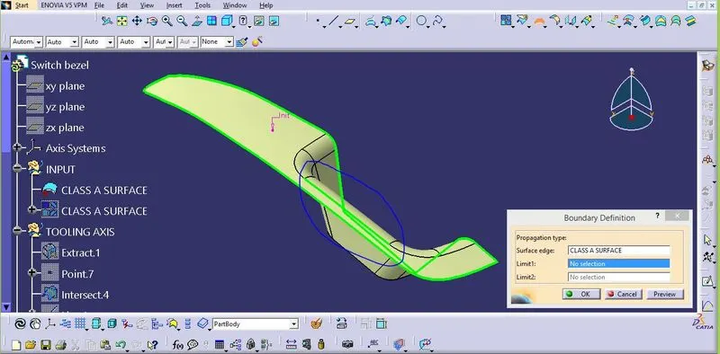
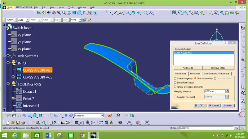
The given input has two boundary so, I change the surface into single boundary surface by applying join command with merging distance .003mm.
Creation of Tooling Axis:
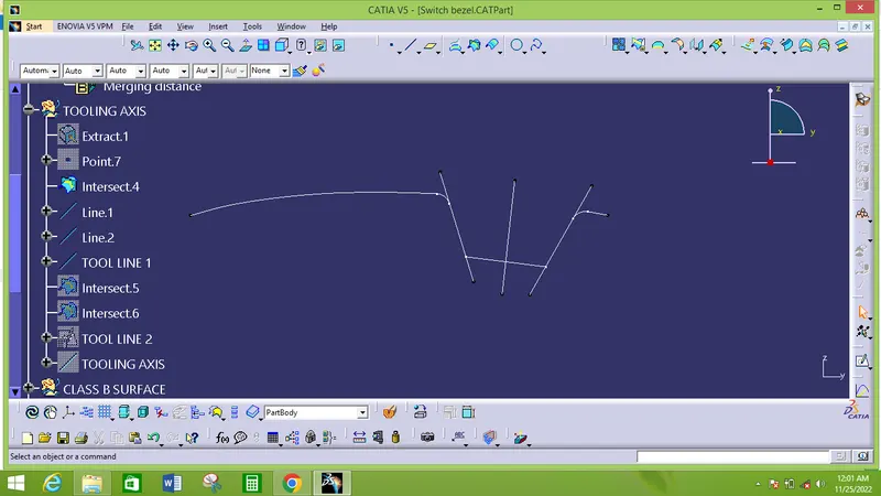
Create an intersection of CLASS A surface with YZ plane and from the intersection create the tooling axis line 1 as shown below.
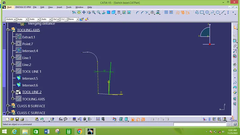
Another tooling axis line 2 create in ZX plane intersection shown like below.
From the Tooling axis line 1 and Tooling axis line 2 the final draft pulling axis or mold open and close axis created shown like below.
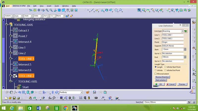
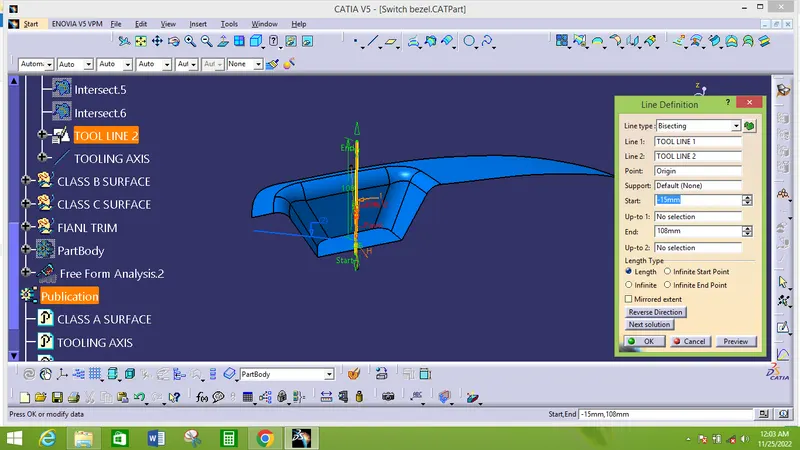
The above shown yellow Line is our tooling axis.
Creation of Class B:
I separated given input surface as 3 sub-surface and named as
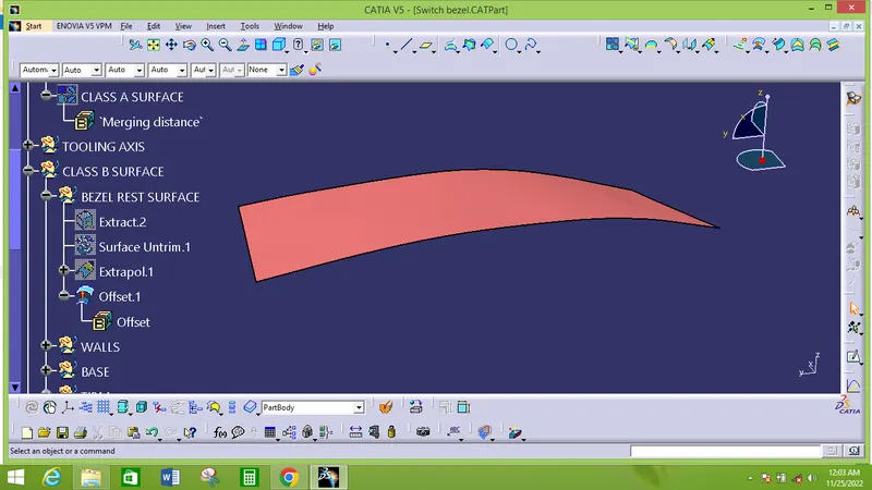
- Bezel rest surface
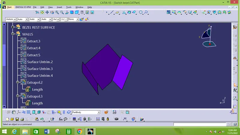
- Wall
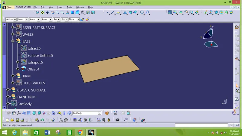
- Base
Sequence of class B surface creation
- Extracted individual surface from Class A and
- Untrimmed them to obtain the original parent surface.
- Then the untrimmed surface Extraplote for required size.
- These surfaces are then offset to the required thickness of 2.5mm.
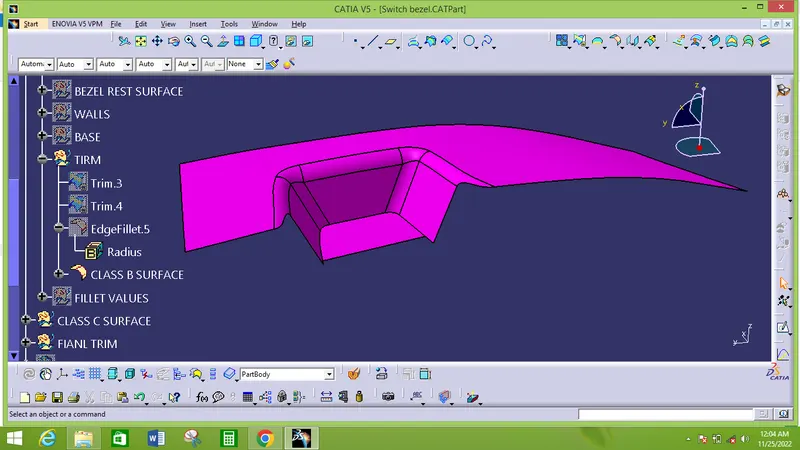
- After offsetting, all the surfaces are trimmed into the required shape.
- Required fillets are given to the surfaces.
Bezel rest surface
Wall
Base
Trimmed class B surface
Class C surrface sweep
- For creating this surface we have extracted the boundry of Class A using multi-extract and then converted to smooth curve.
- Now this smooth curve is swept along the draft direction with a 3deg draft.
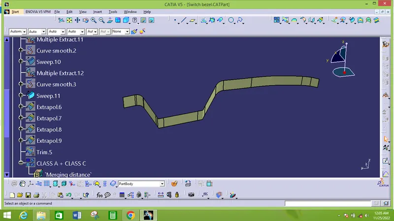
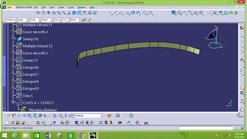
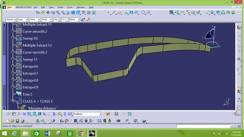
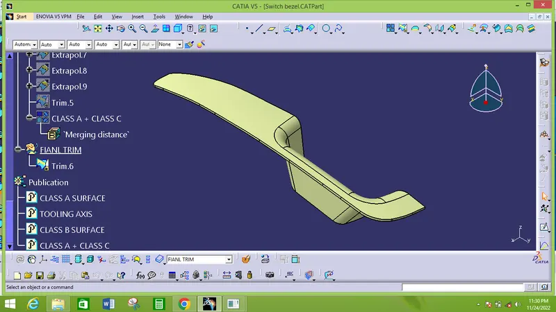
Class A + Class C
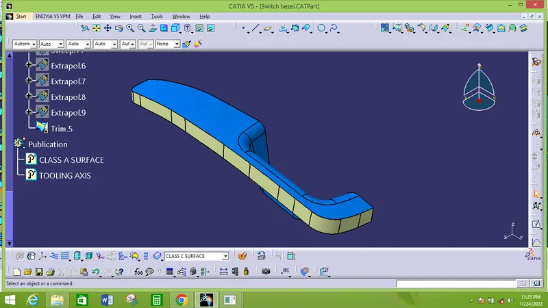
Class A + Class B + Class C
For this we have trimmed the Class B surface with Class C surface using trim feature.
Draft Analysis
Here, draft analysis is done with respect to 3 degree angle.
Class A surface
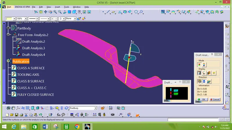
The given input has negative draft.
Final component draft analysis
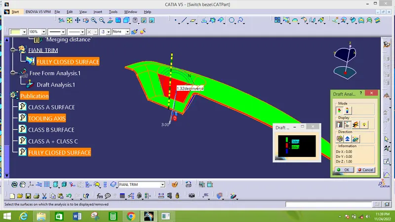
From the above analysis the final component has some surface are having draft angle less than 3 degree. So need to modify the component for mold opening.
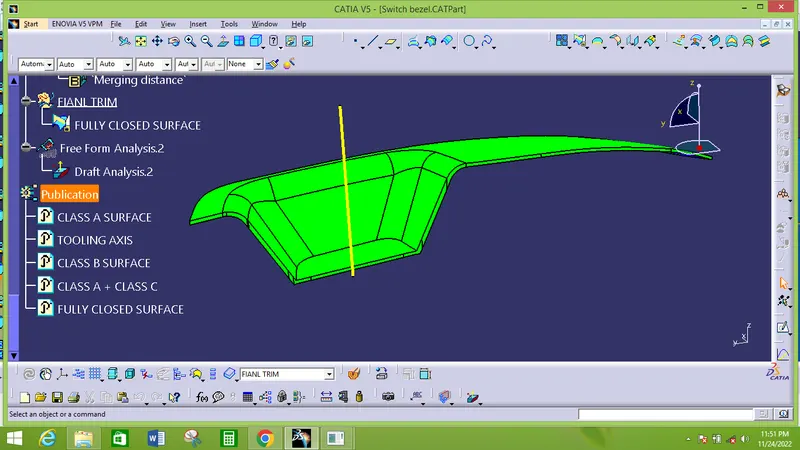
After modification in component the final draft analysis shows that all the surfaces in body are applicable for mold opening without wear.
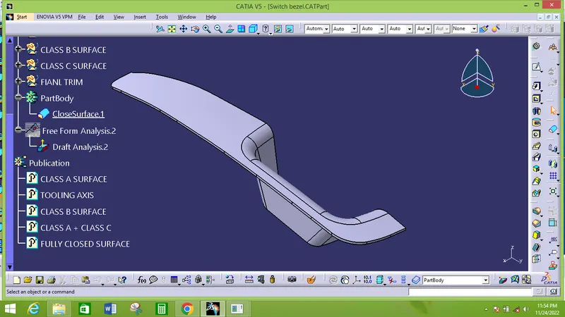
ISOMETRIC VIEW
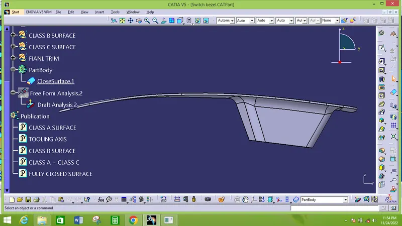
FRONT VIEW
TOP VIEW
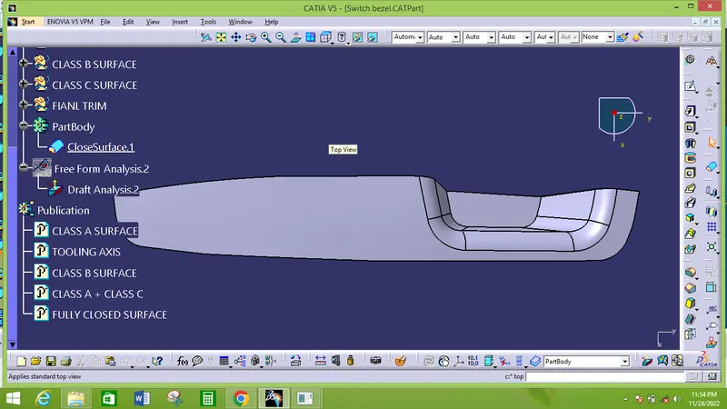
RIGHT SIDE VIEW