Wiring harness design in CATIA V5 - 3D modeling Week 2 Challenge
REPORT ON WIRING HARNESS OF CONNECTOR (DEFINING THEM FROM MECHANICAL PART TO ELECTRICAL PART AND DEFINING THE BUNDLE ENTRY POINT AND CONNECTOR CONTOLR POINT)
What is a connector?
Automotive connectors are a component that very common for electronic engineering technicians. Its function is very simple: it sets up a bridge of communication between the blocked or isolated circuits in the circuit, so that the current flows and the circuit realizes the predetermined function.
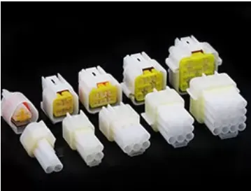
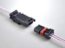
there are various types of connectors are used in automobile industries but today we are going to focus on only converting 3 and 8 terminal connector from mechanical part to electrical part and defining bundle entry and connector control point.
so first we will dowload the CAD file in the form of stp format from TE.com and then we will extract them and then we will open in catia and then we will make further designs.
after downloading the cad file successfully we will open that in catia and then we will make a centre point on both sides of the connector and we will name one point as connector control point which will be in the opposite direction of bundle side and we will name the other point as bundle control point and then we will create a axis on the point of connector control point and we will keep the Y axis as facing opposite side of the point (mating surface) and X axis in the lock direction of the connector and then the Z axis in the left and right direction. and then we willl recieve the output as follows:
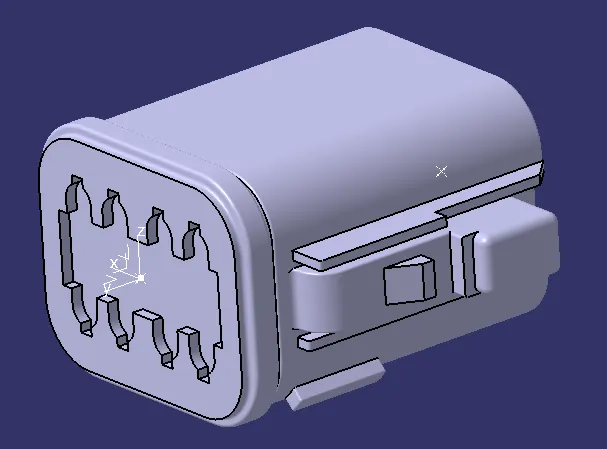
after creating the point and axis we will go to the electrical part design work bench which is present inside the Start-Equipment& Systems -Electrical harness discipline-Electrical part design.
and then we will use define connector command which will convert the cad part from mechanical to electrical part and in the popup window it ask number of terminals and we will give the required terminal as we have and then our paet is defined as a electrical part and our tree structure will somewhat look like the following
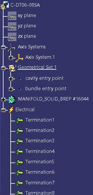
and then we will use define bundle connection point command and we will define bundle connection point and then we will use define connector connection point command and we will define the connector connection point as we define everything in electrical workbench each and every option which we are defining in the electrical work bench is automatically publishing. and the published tree structure is as follows:
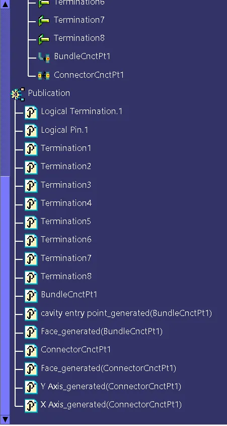
once if we done upto this much for this connector our work is done because our aim is to convert it from mechanical part to electrical part and those bundle and connector points are for assembly when we assemble it with its mating part then we need this points and axis.
now we will conert the other connector to electrical part and its mounting feature also:
as we did earlier we do same here also like we will first download the cad part from TE.com website and then which will be in the form of stp file then we will extract them and then we will open it in catia and then we will do the further operations.
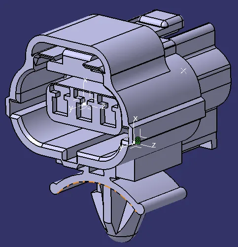
so for this 3 terminal connector also we will do the same. First we will create a centre point on both(bundle side and mating side) aslo and then we will create a axis on the mating point and we will place y axis towards the mating side and x axis towards the locking side and then z axis to the other side and we will recieve the output as follows:
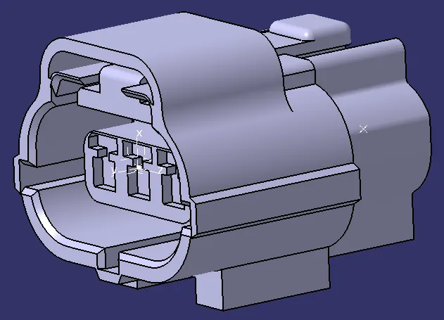
and here we have a mounting feature for this connector so for that aslo we have to create a point and axis so that the mounting feature will come and mount on the connector properly.
if we rotate the model we will have a mouting base in which we will mount the mounting feature so for tht first we will create a midpoint(cavity connection point) and then we will create a axis in which the y axis will be on the mating side and the x axis will be on the locking side and the z axis will be on the rest side.
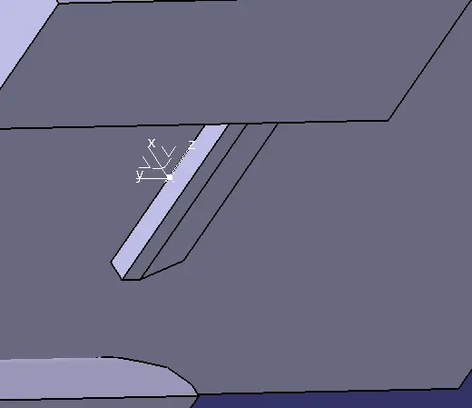
and then we will move to electrical part design workbench and then first we will define the connector using define connector command and then we will define the bundle connection point and then we will define the connector connection point and eventually make it as a electrical part.
after this we will define its mounting feature as electrical part for that also first we will download cad part and then we will work on it.
first we will create a point on its mounting surface and then we will create a axis and we will place the xyz axis as it has to be place according to it mating part and then we will move on to the electrical part design workbench and then we will define it as a electrice paet using define mounting equipment command and then we will define the cavity instead of using define cavity point we will use define cavity command and define the whole cavity and then we will recieve the output as follows:
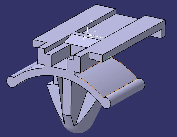
and now we have define both components as electrical parts now we have to assemble both of them and the assembly is way simple than this all.
first we will move to electrically assembly design workbench and then we will add both the components in it and then we will bring the mounting feature close to the connector and we will use connect electrical devices command and then we will selsct the face of the mounting feature which has to be mounted on the connector and then we will selc the connector and we will recieve the output as follows:
by this way we have successfully defined each and every part from mechanical to electrical part and sucessfully we have assemble the connector and the mounting feature aslo.
NOTE: OPEN AND HAVE A LOOK AT ALL THE SUB FOLDERS INSIDE THE MAIN FOLDER