Wiring harness design in CATIA V5 - 3D modeling Week 2 Challenge
AIM:
Download following Connectors & Connector clip cad data from given link & define it as Electrical Connector using Electrical Part design Workbench. Define all the necessary properties to Connectors & Clip.
Connector Definition Following Parameters are required to defined for any Connector -
Geometry Parameters - Points & Co-ordinate system (Axis)
Connector Connection Points - This Point is used for the Connection of one Connector to another Connector.
Harness bundle entry Point - This Point defines where the harness bundle segment Point will end when routed to the electrical Connector.
Cavity Connection Point (Optional) - This Point is used to define the Connection of a Connector to a Connector clip. This only applies to Connectors which have the mounting feature for a Connector clip.
CONNECTOR DEFINATIONS IN CATIA V5
Below Steps need to be followed to define Connectors and Connector Clip as Electrical Connector using Electrical Part design Workbench.
1. Create/Download Connector 3D:
2. Create Required Geometrical Parameters:
3. Define Part as Connector:
4. Define "Bundle Connection Point":
5. Define "Connector Connection Point":
6. Define "Cavity Connection Point" (if applicable):
CONNECTOR DEFINATIONS IN CATIA V5
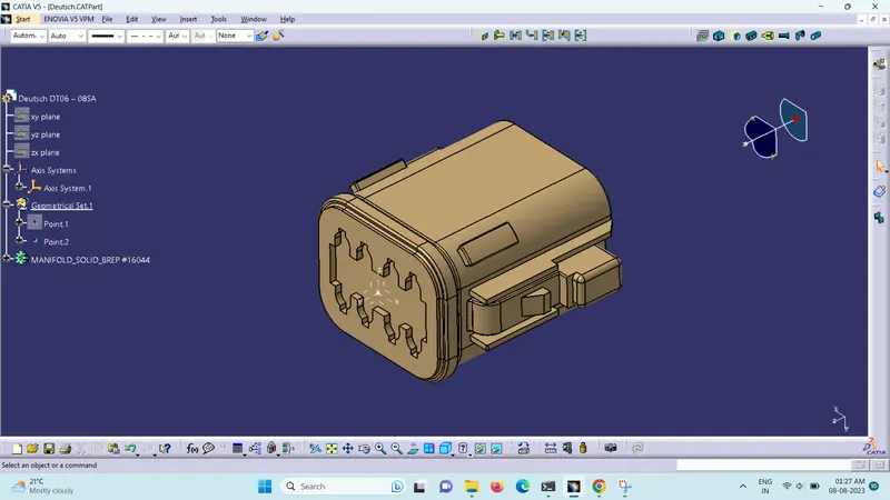
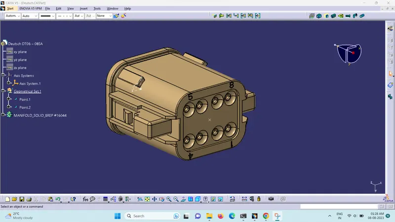
1. Deutsch DT06 – 08SA
Connecctor Connection point & Axis
Bundle Entry Point
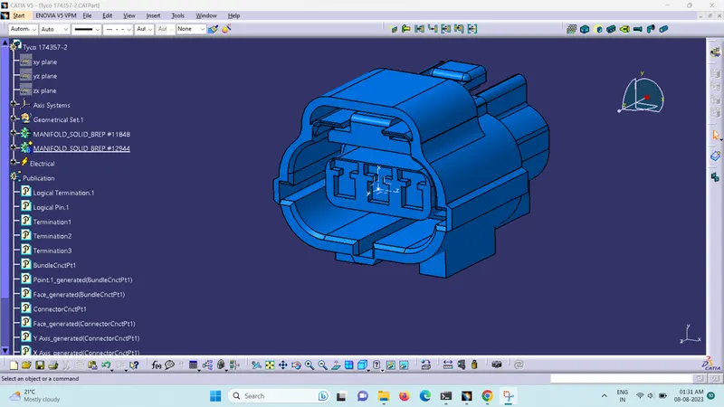
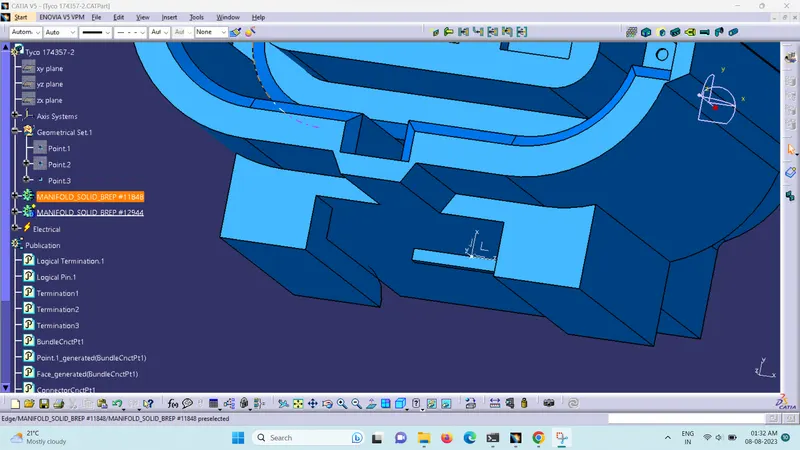
2. Tyco 174357-2
Connecctor Connection point & Axis
Bundle Entry Point
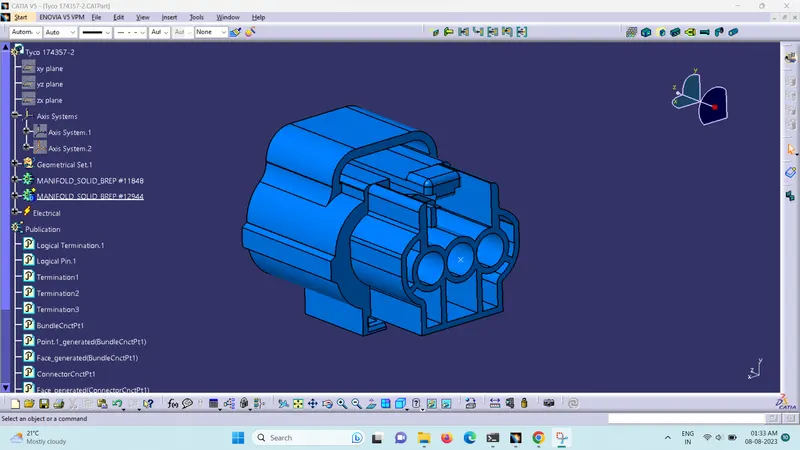
Connector Cavity Connection Point & Axis
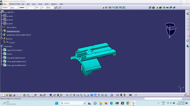
3. Tyco 85229-1
Cavity Connection Point & Axis
CONCLUSION - The connectors are electrically defined and stored in the Catalog.