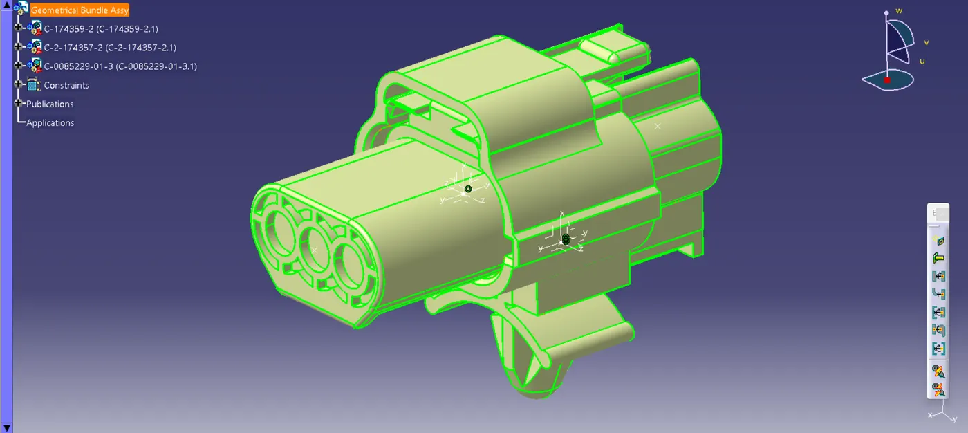
Wiring harness design in CATIA V5 - 3D modeling Week 2 Challenge
step 1:
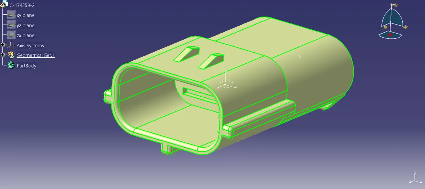
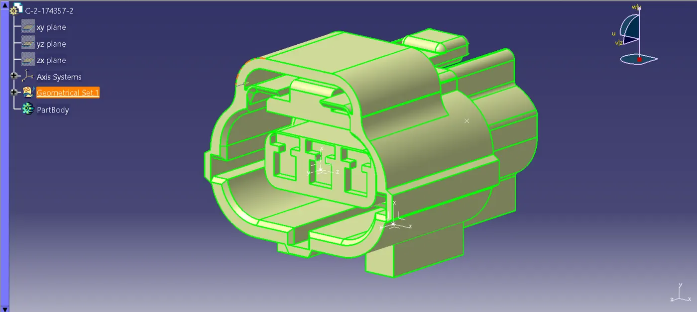
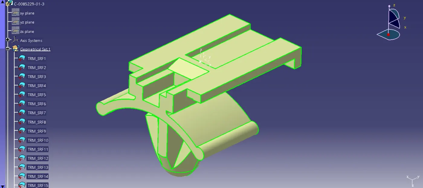
Downloading and importing .igs files of electrical component required for electrical assembly and saving them as an individual parts accordingly secondly adding the required geometrical features to them to them such as points, axis system etc.
step 2:
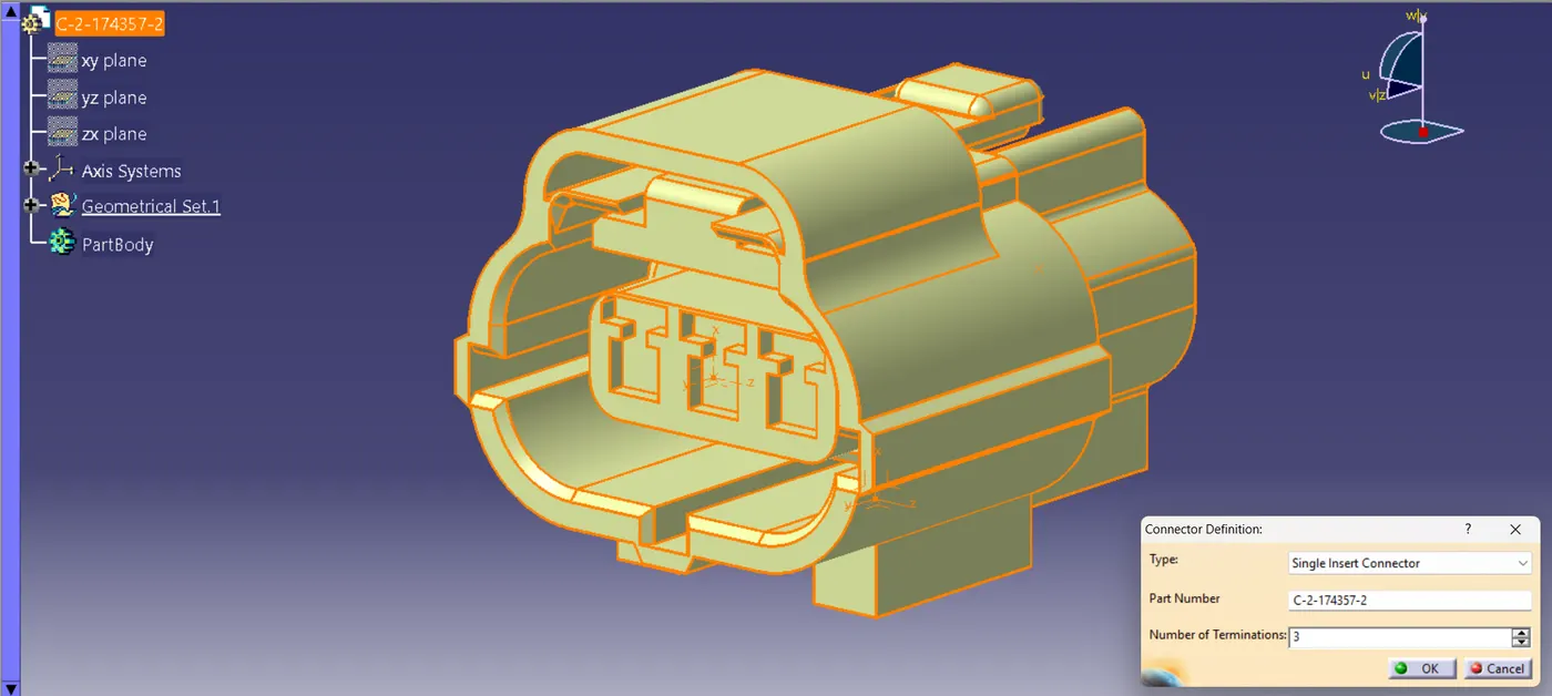
The next step is to define them as an electrical component. Go to>> Electrical part design workbench
select 'connector definition' command to define electrical connector and select no of terminals as 3.
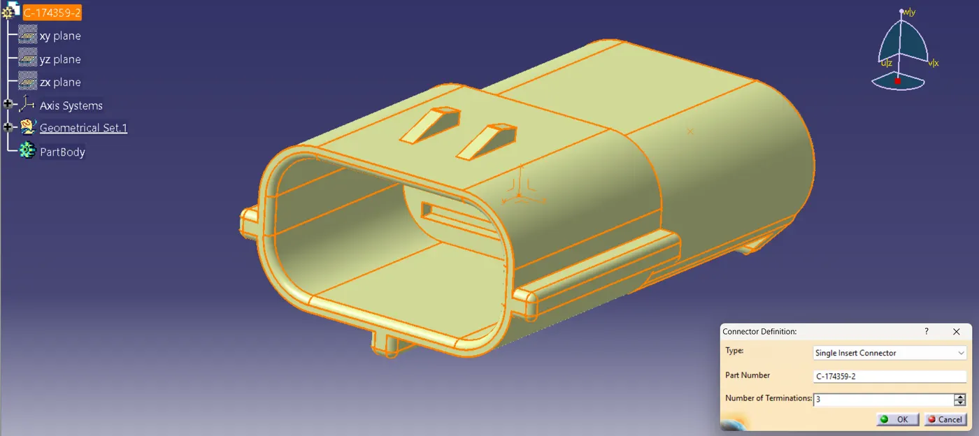
step 3:
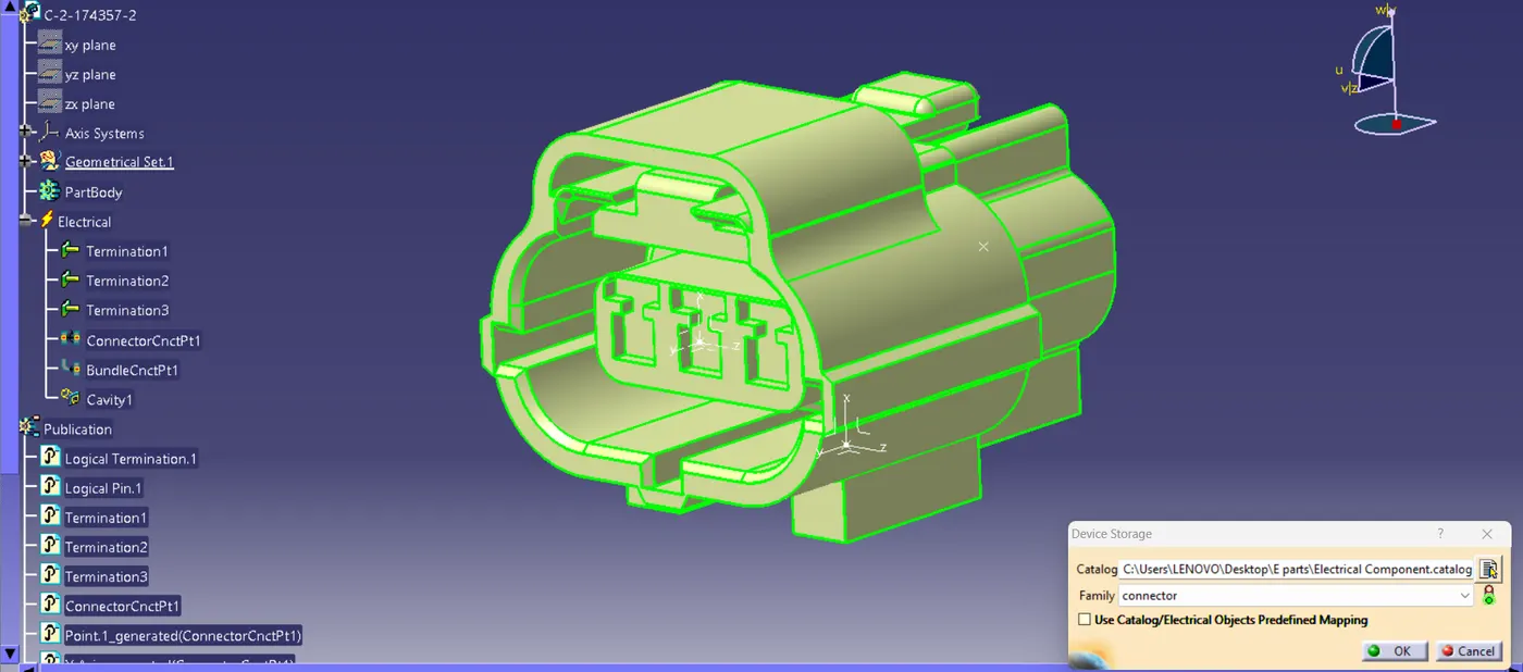
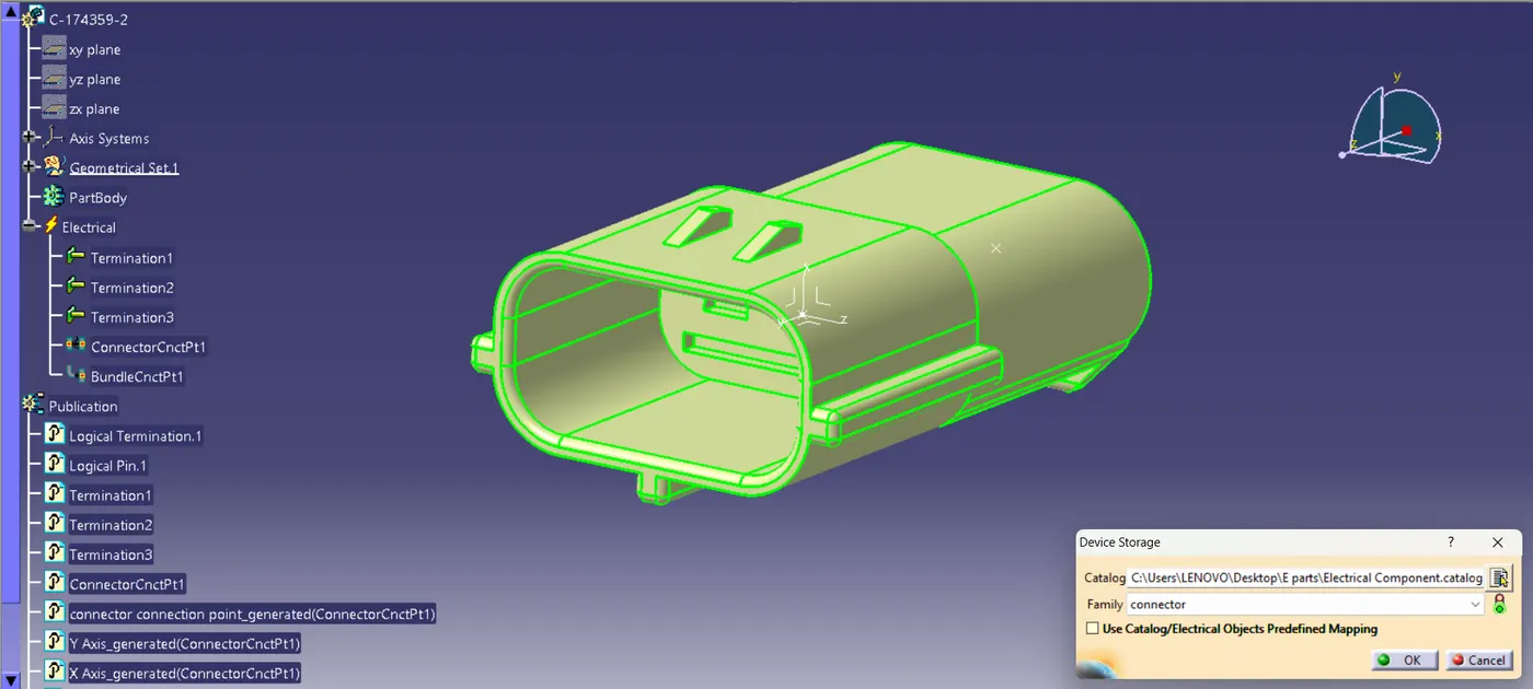
After defining the part as an electrical now it's time to add electrical properties to them using command connector connection point & bundle connection point using geometrical properties.
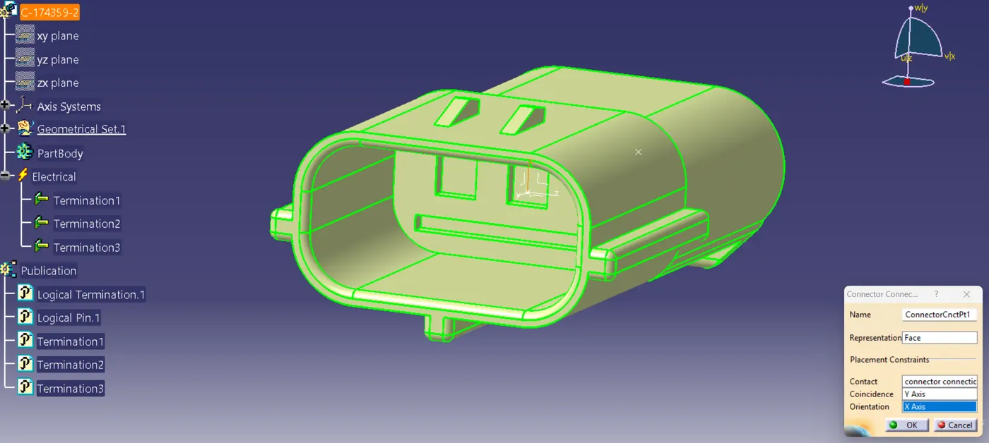
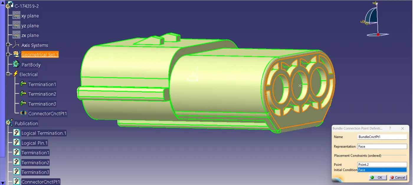
In the below image you can see the connector is now electrically defined and all required electrical properties has added.
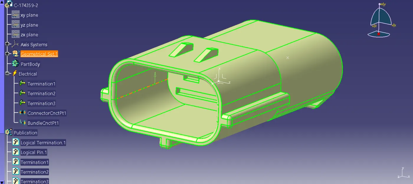
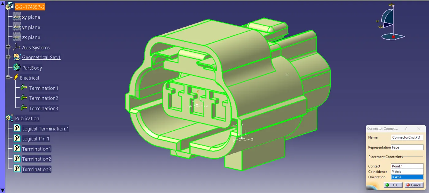
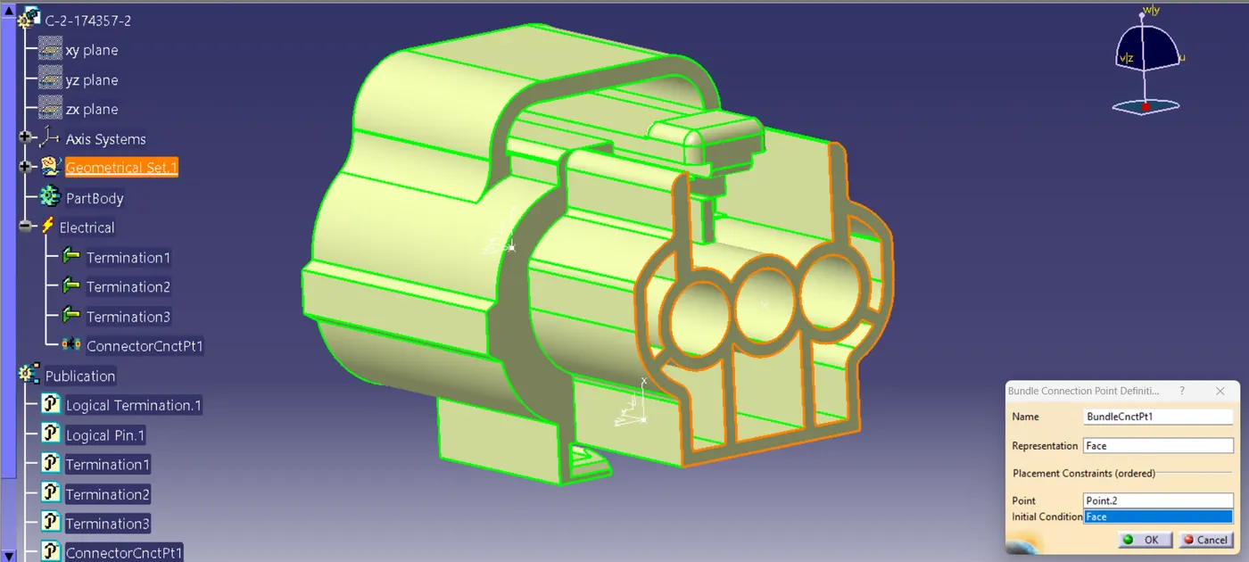
step 4:
In this case it is necessary to define cavity connection point in the female connector for clip mounting
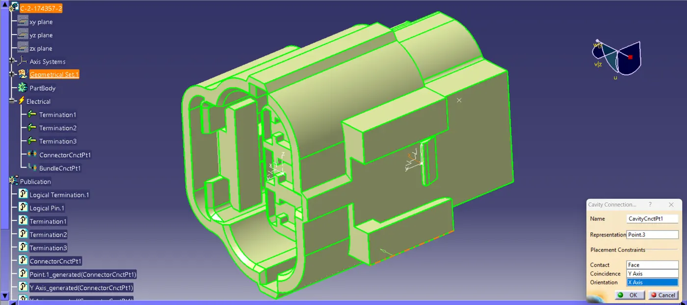
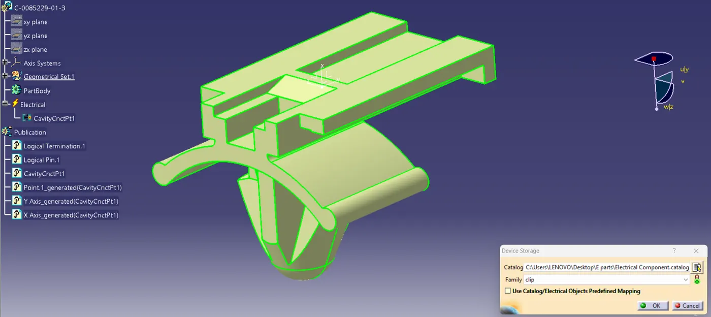
similarly needed to define cavity point in the mounting clip for connection with connector
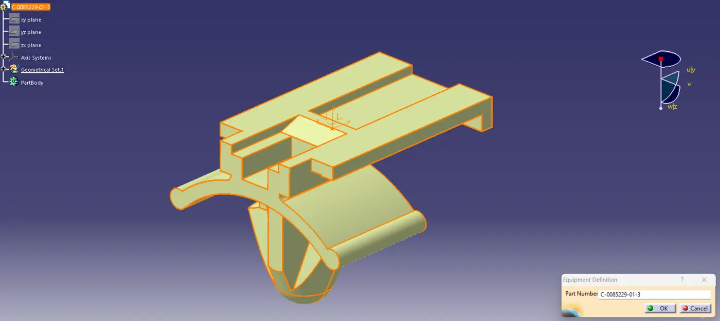
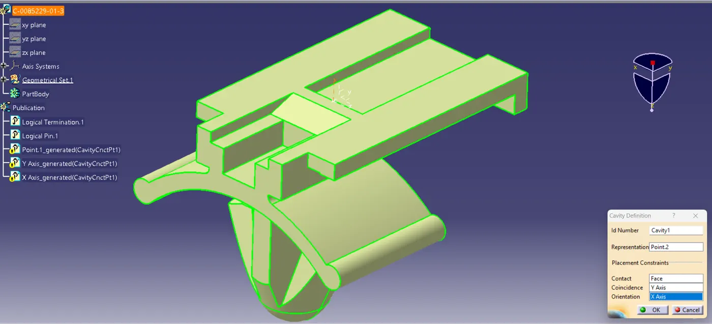
Note:
The axis orientation should be same in connector & mounting clip as shown in image.
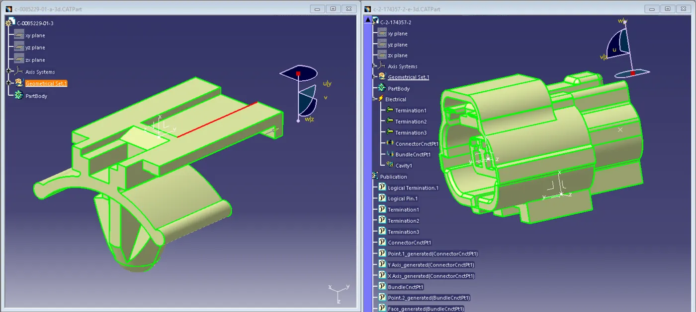
step 5:
Creating a catalogue and adding electrical components using store device command to it for future use.
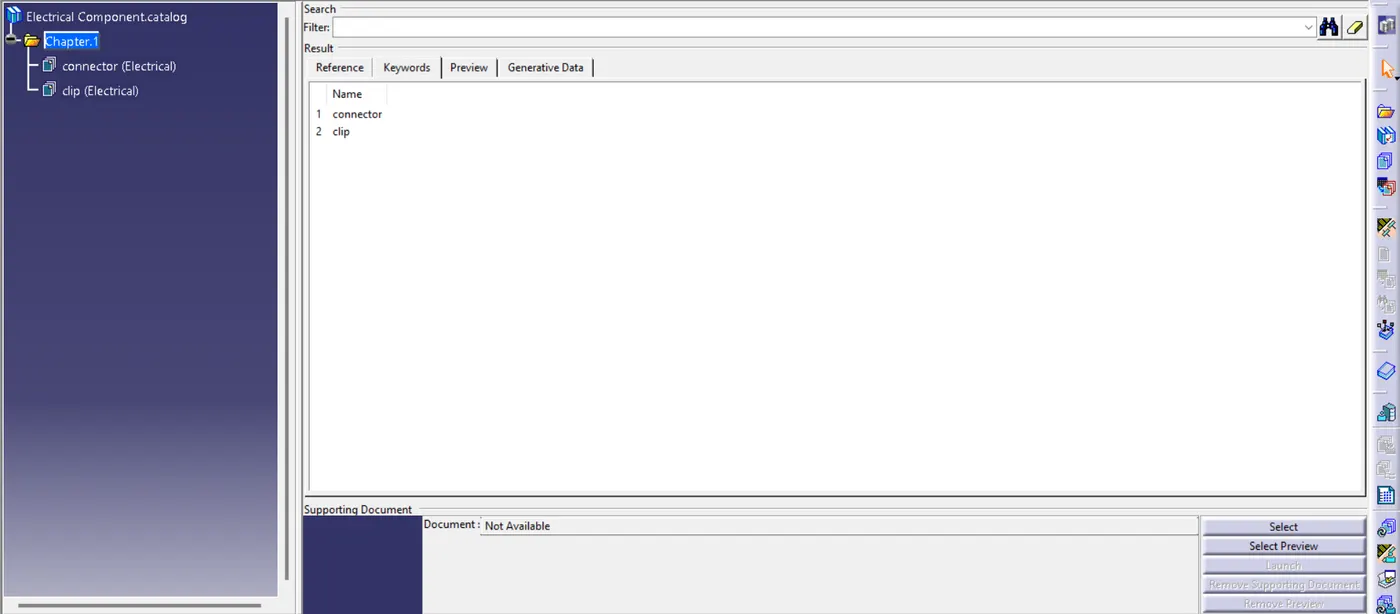
step 6:
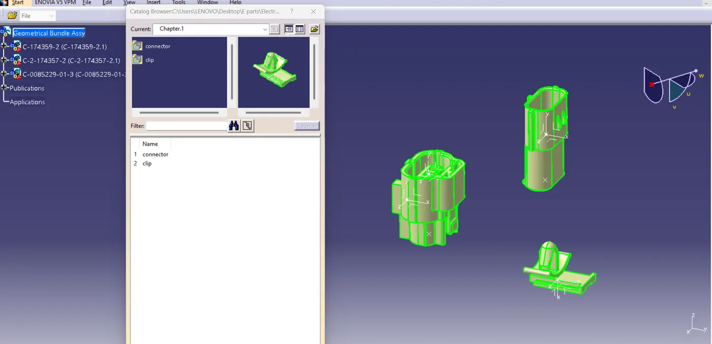
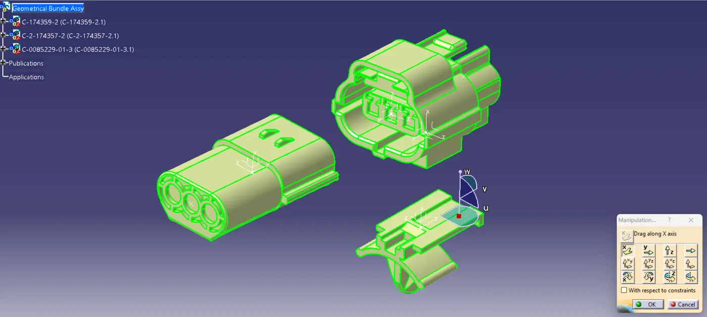
In the next step creating a Product file and renaming it as 'Geometrical Bundle Assy' and adding electrical parts from catalogue.
step 7:
Locating the components at desired location using manipulation tools present in mechanical assembly.
Now Go to>> 'Electrical Harness Assembly workbench' to define the assembly as an electrical assembly.
step 8:
Finally, by using connect electrical devices command in the electrical assembly workbench connect the connector connection with another connector and mounting clip.
Now the Electrical assembly is complete.