Week 9 - Challenge 2 - Switch Bezel Design
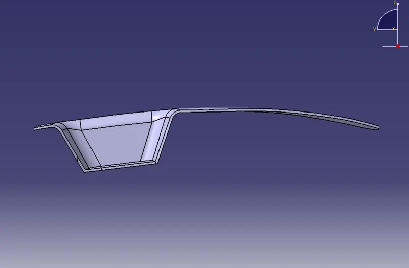
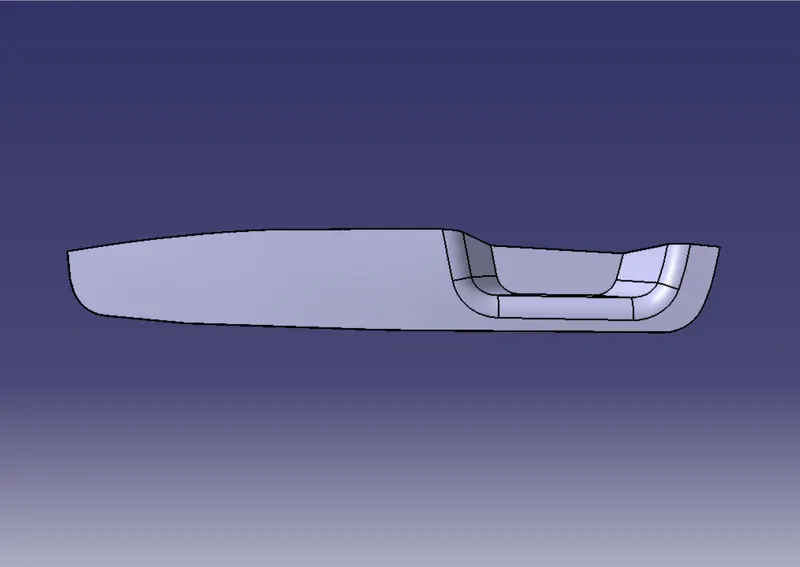
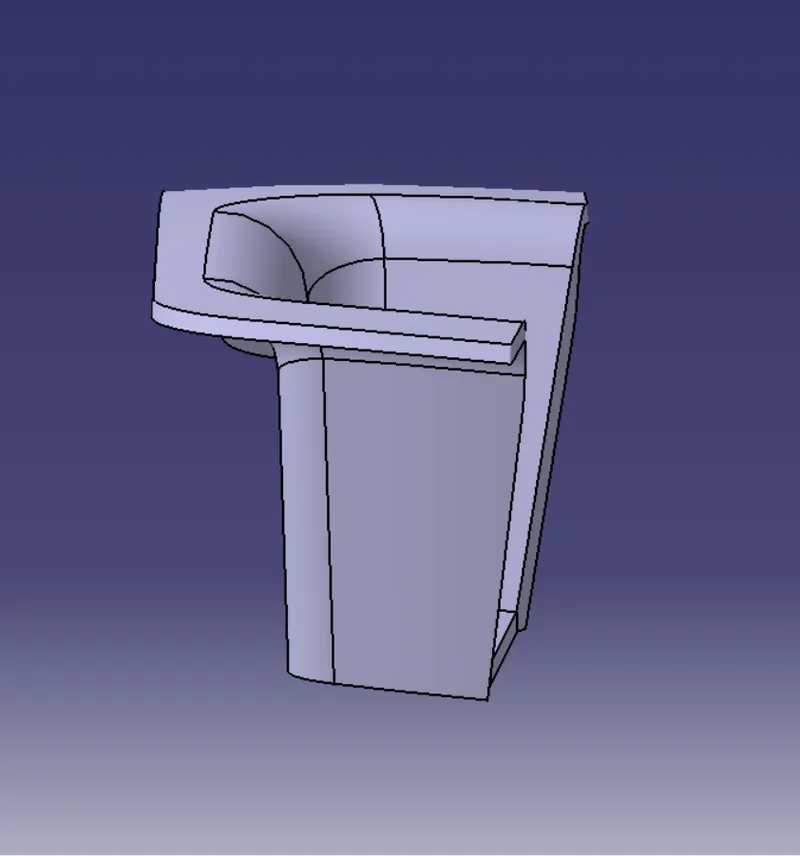
- AIM: Create the Switch Bezel Plastic component through the given Class-A surface. To begin with, the tooling axis for the given Class-A Surface should be created meeting the requirements of the draft angle and at the end perform the Draft analysis on the model. Take the Thickness of the component to be 2.5 mm
- INPUT CLASS-A SURFACE:
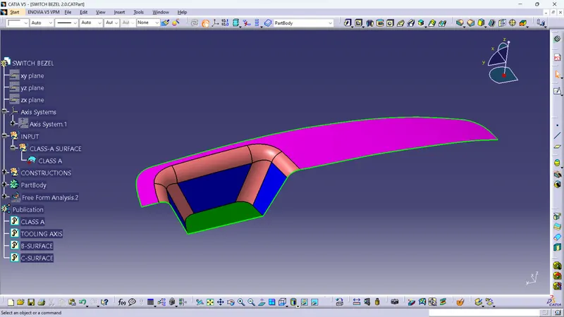
PROCEDURE:
1. CREATING TOOLING AXIS:
- Extracting bade surface fron class-A and untreame it.
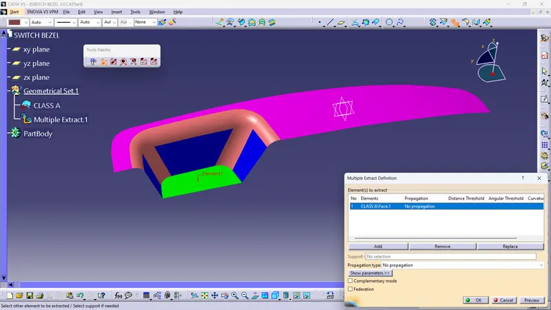
- Add point on the surface such that insert axis system on it
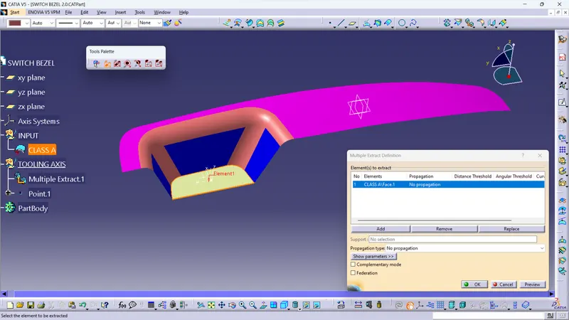
- select positioned sketch in yz direction,took referance from class-A
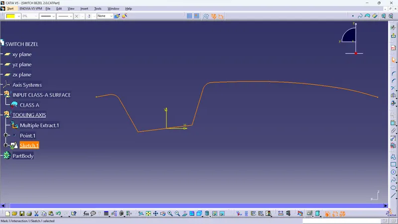
- insert two lines on two inclined edeges and bisect them
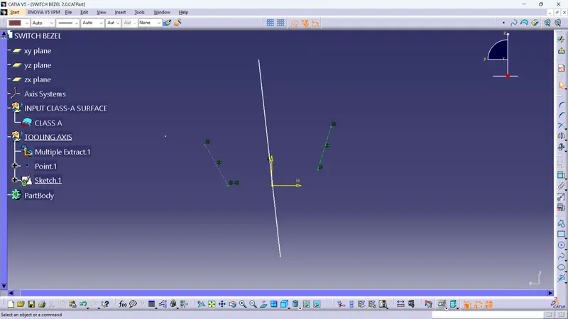
- repeat same steps for xz direction
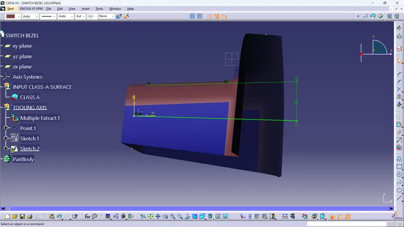
- now take bisector of bisecting lines in x & y direction for final Tooling Axis.
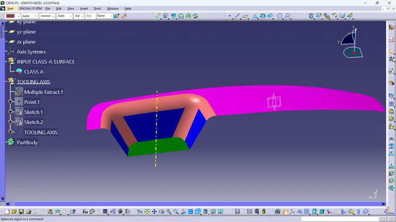
- Note: publication of class-Asurface and Tooling Axis should be done after this step.
2. CREATION OF B-SURFACE:
- Switch bazel, walls, base
- Extract the top surface from class-A and name it switch bazel
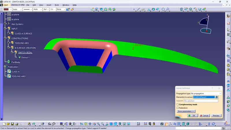
- untreame the extracted surface
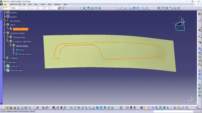
- similarly do it for walls and base feature
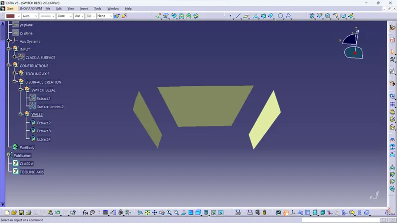
- faces looks smaller in size Extrapolate them
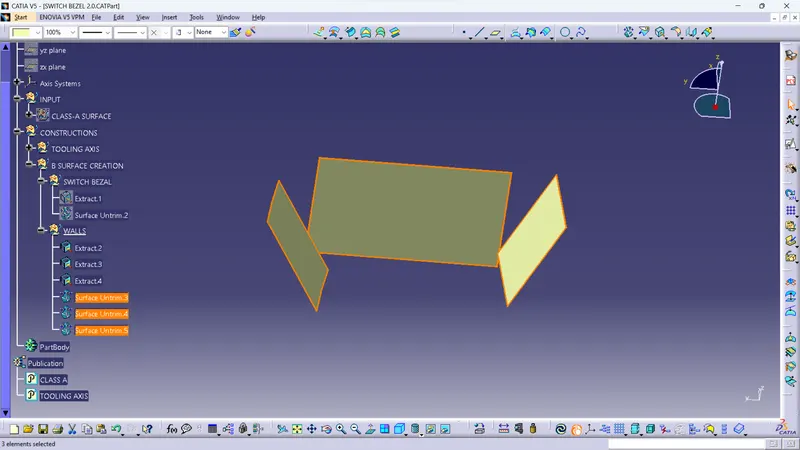
- unhide the switch bazel also and trim the faces with respect to each other
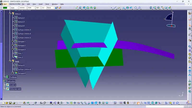
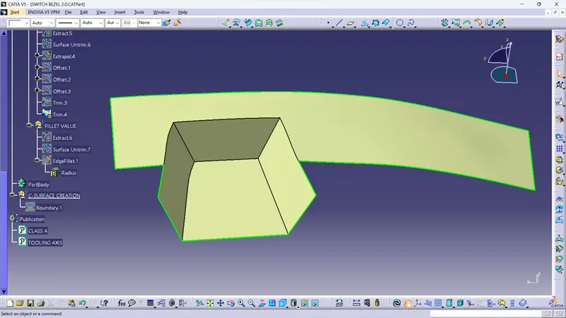
- finally fillet the sharp edges of the surface with sutaible radius of 15mm and will get B-surface
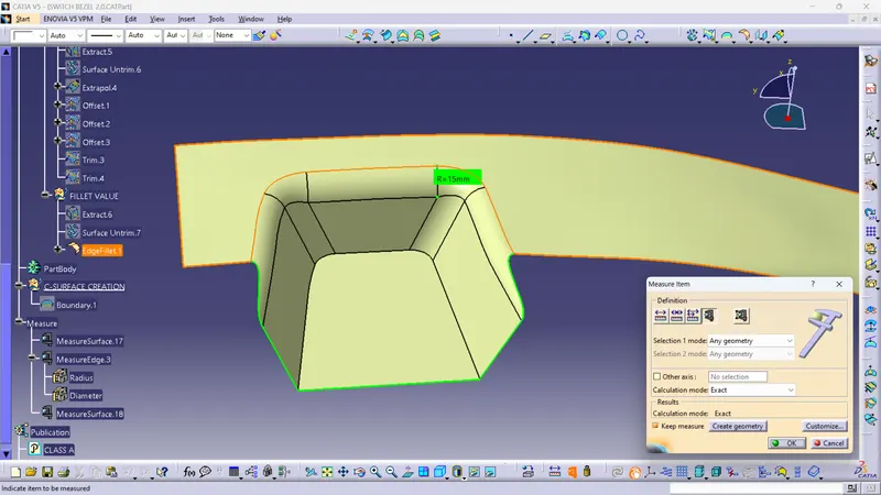
- exact fillet radius should be corrected for final surface.
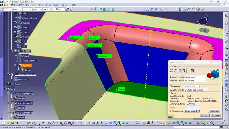
3. CREATION OF C-SURFACE:
- take the boundry of class-A surface using Boundry cammand
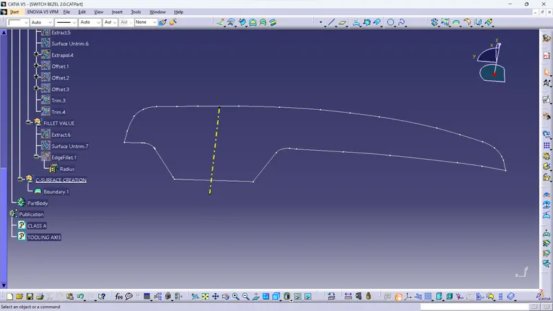
- next step is using Sweep cammand use draft with surface option and draft it ti 3 degree for C-surface
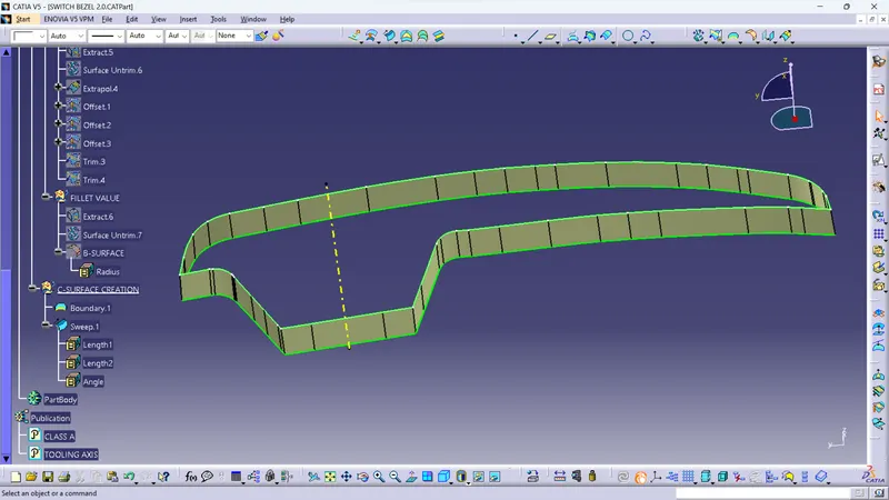
- Insert and replace smooth curve cammand with Boundry Cammand in tree structure
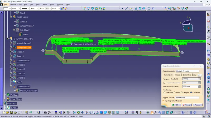
- finally got the smooth and fine C-surface with minimun patches
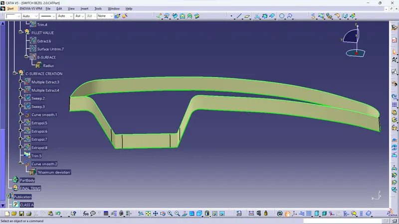
4. TRIM OPTION:
- Now join the class-A and C-surface using Join cammand
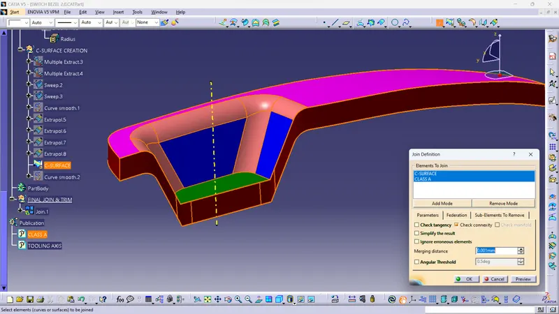
- then Trim the joined surface with respect to B-surface
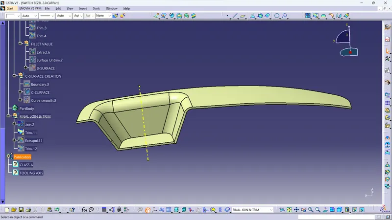
- finally insert body and use Close Solid option to make solid model
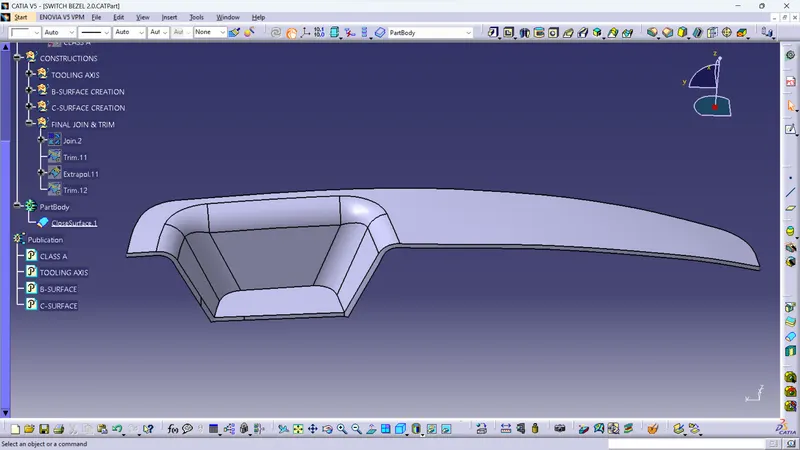
5. DRAFT ANALYSIS:
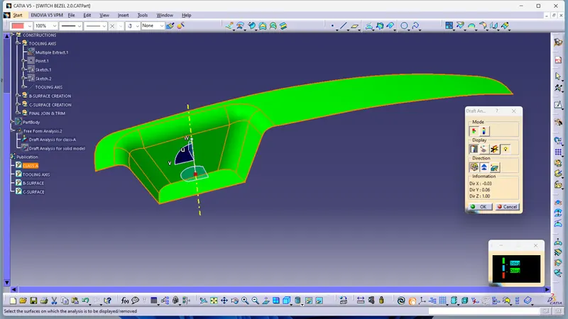
- FOR CLASS-A SURFACE:
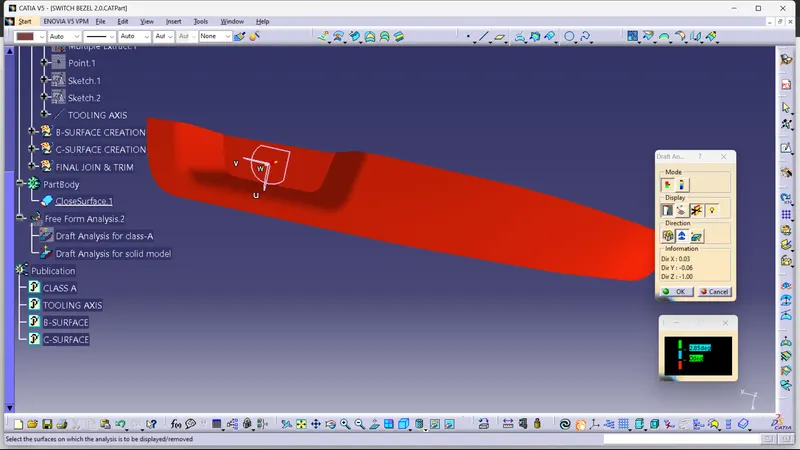
- select Analysis > feature Draft Analysis option from toolbar
- select element for analysis
- drag compass and align with tooling axis
- and do the draft analysis of class-A surface.
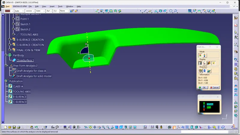
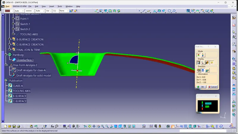
- FOR SOLID MODEL:
- select element for analysis
- drag compass and align with tooling axis
- check and analyse the graft given for solid model
- nominal draft is 2.85 degree.
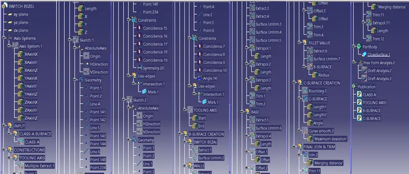
- DETAILS VIEW OF TREE STRUCTURE:
- Screenshots of the solid model with the proper color code of the draft angle in various orientations (Isometric, Front, Side, and Top View):
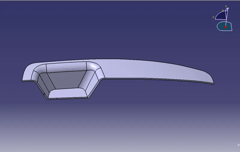
- CONCLUSION: In this way completed the challange of Creating the Switch Bezel Plastic component through the given Class-A surface.