Week 9 - Challenge 1 - Base Bracket Design
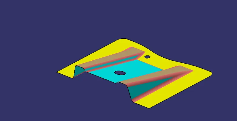
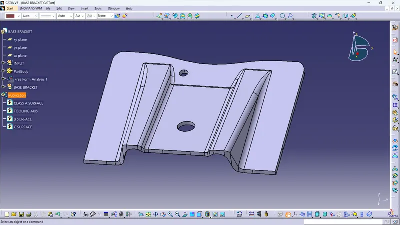
- AIM: Create the Base Bracket Plastic component through the given Class-A surface. To begin with, the tooling axis for the given Class-A Surface should be created meeting the requirements of the draft angle and at the end perform the Draft analysis on the model. Thickness of Plastic Part - 2.5 mm
- GIVEN CLASS-A SURFACE:
- PROCEDURE:
- CREATING TOOLING AXIS:
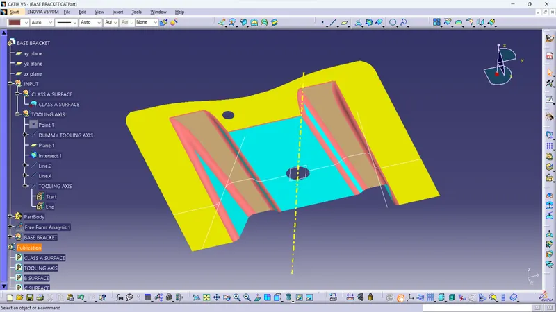
- frist check which direction would be best suitaible for tooling axis in this case it is z-direction (z-axis)
- Add a Point at centre of hole located on class-A surface.
- Insert an imagionary axis along it.
- Insert plane for bisecting in y-direction.
- Now, select the Intersect cammand and bisect the class-A surface along yz plane.
- you got a profile made up of lines and curve. ignore the stuff except the draft line (inclined lines) which may create problem for tooling axis, pick them and insert line along them for both RH and LH side of dummy axis.
- now in line cammand use a bisecting option and select those two line one by one and hide dummy axis and choose bisector axis for z-axis.
- this is the procedure of Tooling Axis for part we need to manufacture.
2. DRAFT ANALYSIS FOR CLASS-A SURFACE:
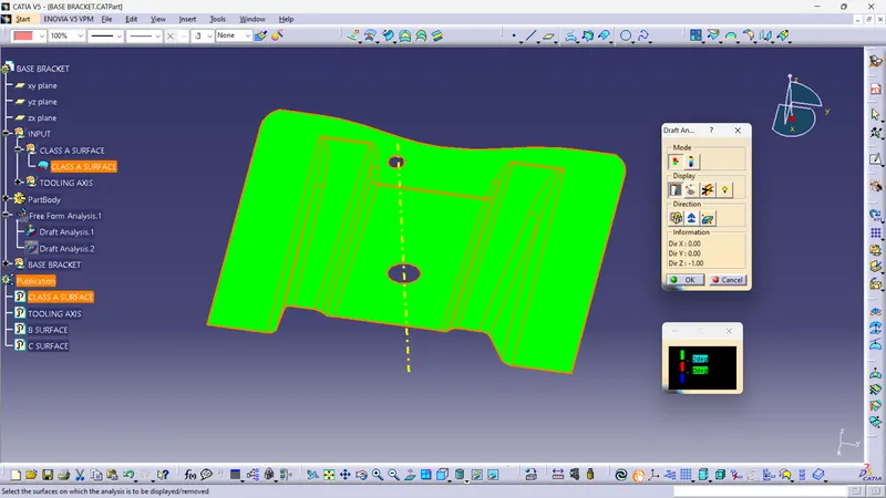
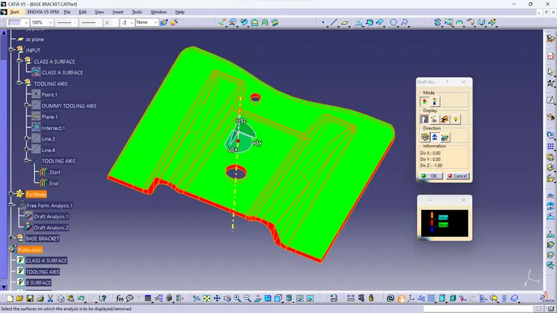
- After creating Tooling axis go for draft analysis
- insert> Analysis> feature draft analysis
- select element to analyze.
- click on Use the compass to define the new current draft direction option and make it align with the tooling axis by dragging it to the axis
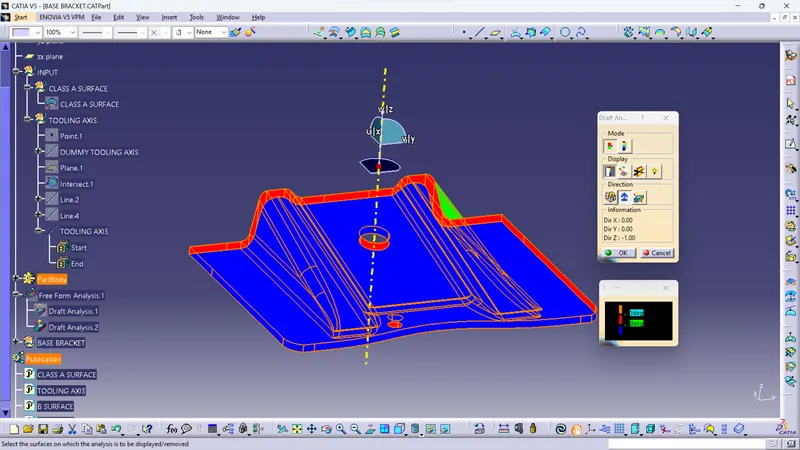
- If the color appears blue just click the invert option on the right side of the draft direction axis button
- also check draft at diffrent faces of class-A Surface.
- NOTE: Publication of class-A & Tooling axis.
3. CREATING CLASS-B SURFACE:
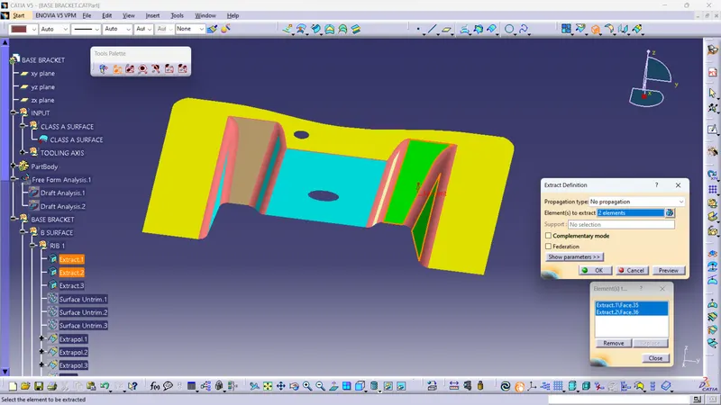
RIB 1&2, BASE
- Using the Extract option select the first set of ribs from the Class A surface
-
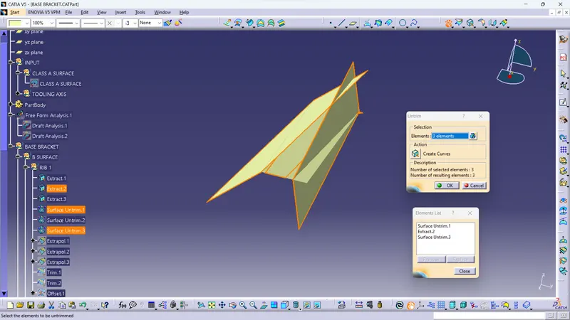
Then use the untrim surfaces command to restore the surfaces up to the limit.
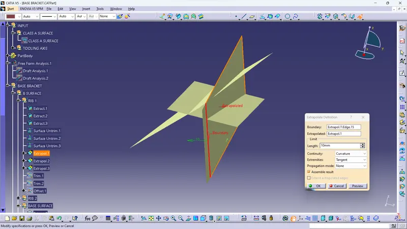
- After that click the Extrapol command to extract the surface in the curvature direction.
-
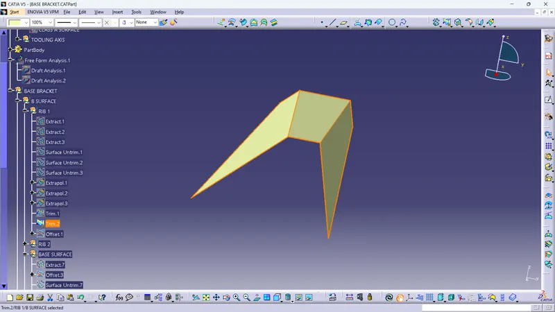
then use the trim command to cut the surfaces to get the desired output.
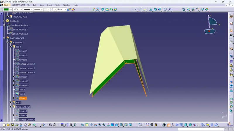
- finally offset the trim face by 2.5mm
- Similarly, do the same process for the second rib. We get the following parts.
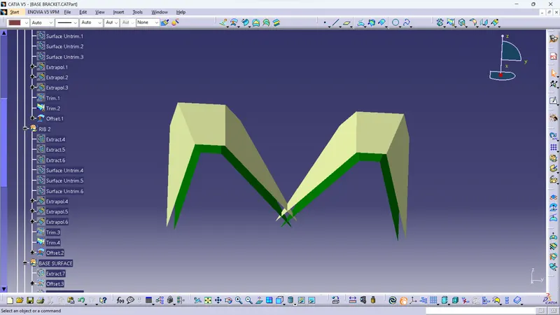
- repeat similarly Extract> Untrim> Extrapol> Trim> Offset for Base surface and middle surface we get;
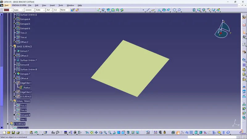
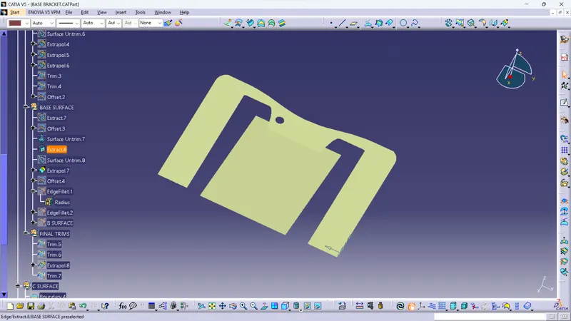
-
Now all the parts are trimmed to get a Class B surface join them all and fillet the edges by 3 mm and we get Class-B Surface.
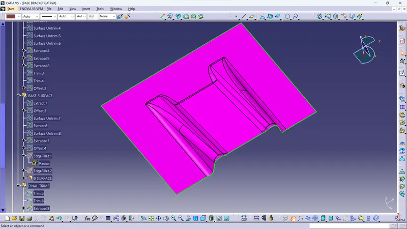
4. creating Class-C Surface:
- Select the boundary option and click on the boundary of the class A surface to create a sketch of the boundary.
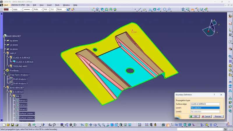
- The Boundry.
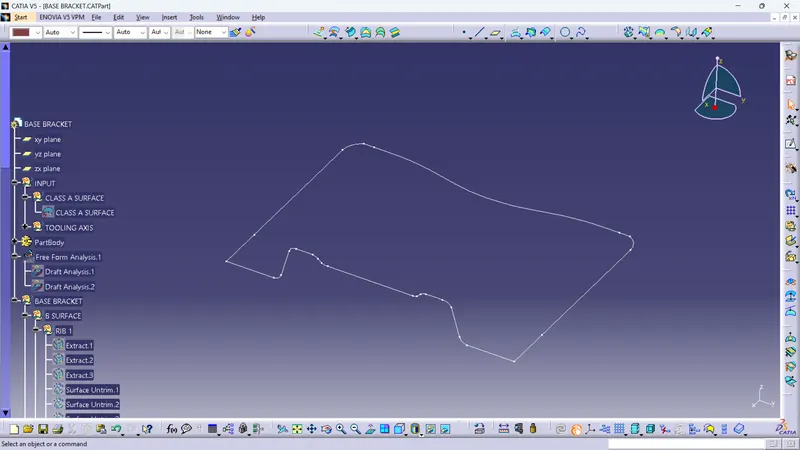
-
Using sweep command select with draft direction option and set a 3-degree draft to create a sweep of the boundary in Z-axis with angle.Select the appropriate direction to get the draft.
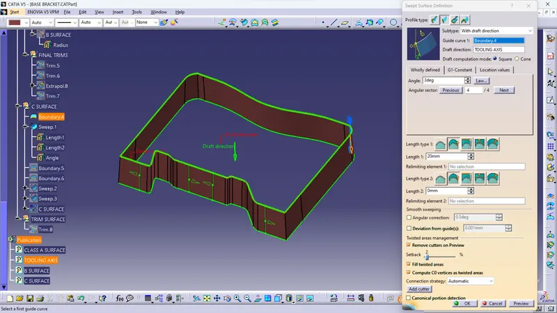
- similarly do the same for two holes also.
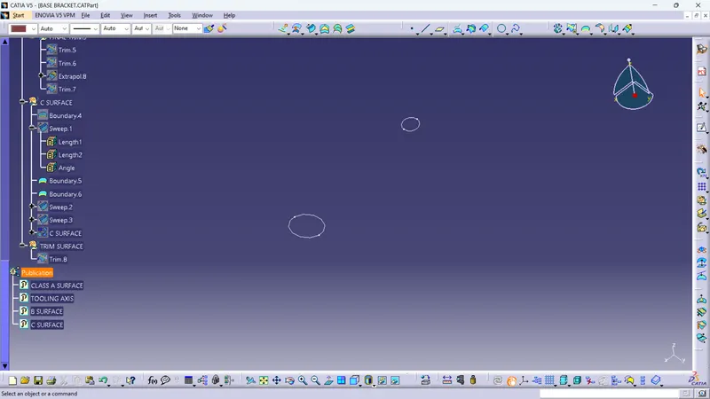
- after swept with draft surface w'll get the following two also.
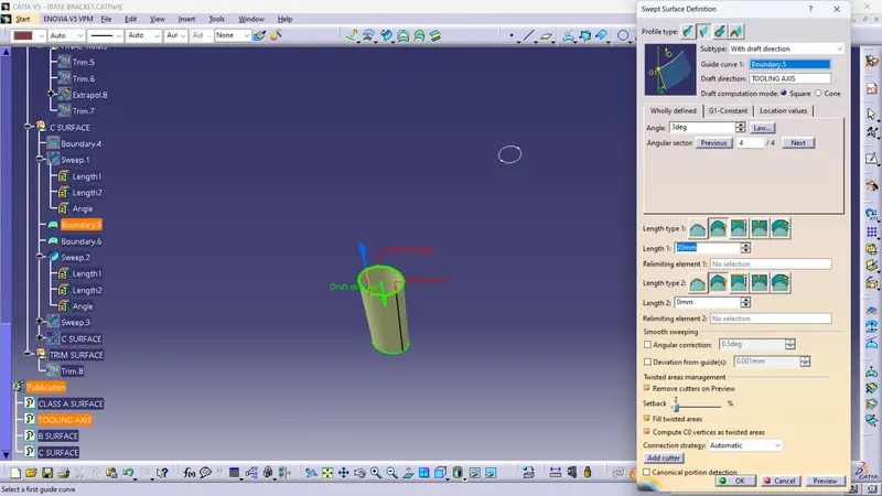
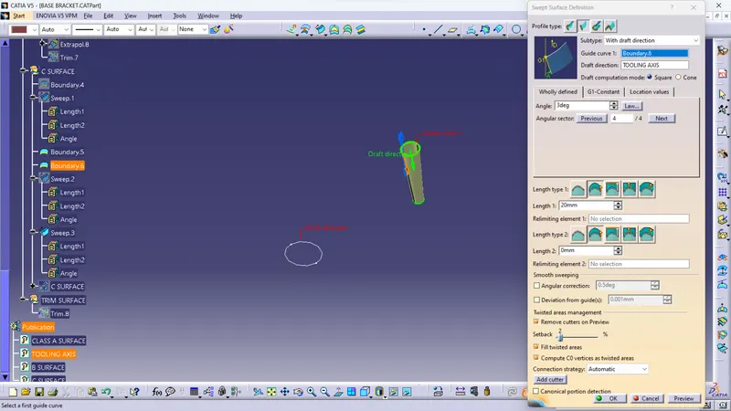
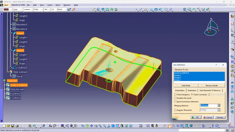
- Join all the elements together.
5. THICKEN BASE BRACKET:
- finally, trim C-Surface with respect to B-Surface for 2.5mm surface.
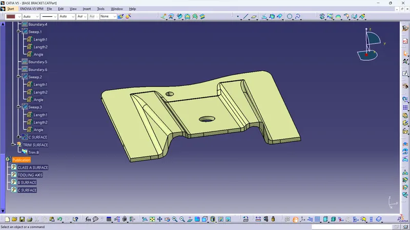
- Using the Closed Surface option create a solid part of the bracket.
6. DRAFT ANALYSIS ON SOLID PART:
- select element to analyze.
- next click on the compass to define new current draft direction option and align with the tooling axis by dragging it to the axis.
- and check wheather the appropriate draft is correct or not analyze it.
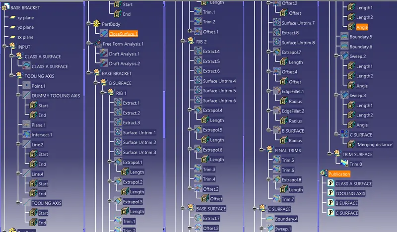
- DETAILS OF TREE STRUCTURE:
- SOLID MODEL VIEW:
- ISOMETRIC VIEW:
- FRONT VIEW:
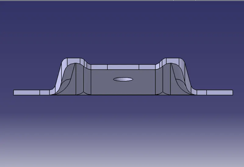
- BACK VIEW:
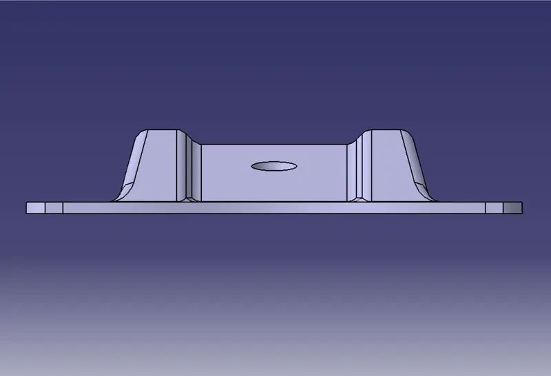
- SIDE VIEW:
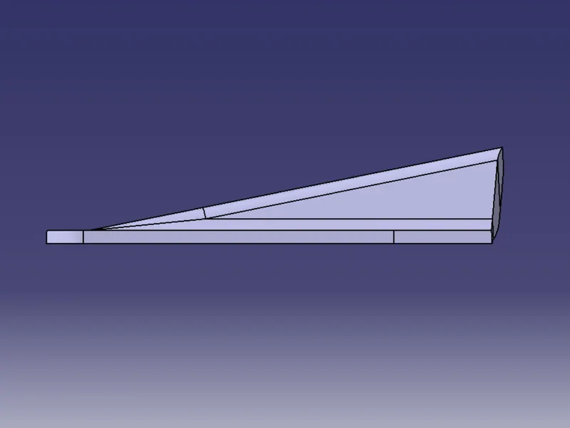
- TOP VIEW:
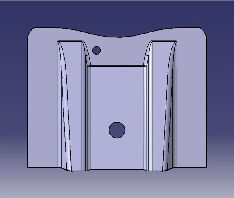
- CONCLUSION: In this way created a Base Bracket Plastic component through a given class-A surface analyzed the surface with 3mm degree of draft angle.