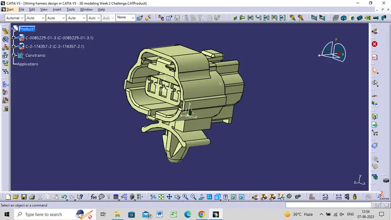
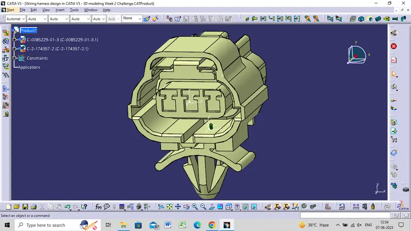
Wiring harness design in CATIA V5 - 3D modeling Week 2 Challenge
Aim
To Download the following connectors & Connector clip cad data from the given link & define as Electrical Connector using the Electrical Part Design Workbench. Define all the necessary properties of Connectors & clips.
DT06-08SA
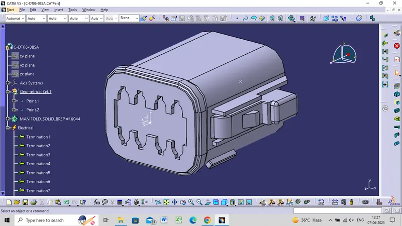
- Defining geometrical properties (points and axis system)
- Bundle entry side center point.
- Selecting two random points diagonally to get a center point.
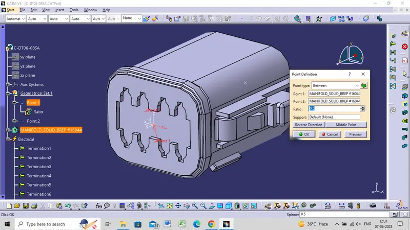
Mating side axis system
- Creating an axis system concerning the center point as the origin of the axis.
- The Y axis is directed at the mating direction, the X axis is directed towards the locking side and the Z axis is directed upwards.
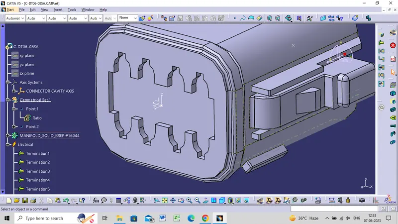
Electrical Part Design Workbench
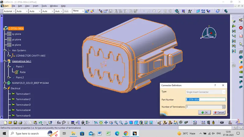
- Define part as a connector
- Defining part as an electrical connector under Electrical Part Design Workbench. Selecting the number terminations 8.
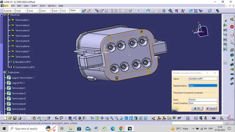
Define bundle connection point (bundle/wire entry side)
Defining bundle connection point at the bundle entry side where, representation is the face, point as the center point, and initial condition also as the face.
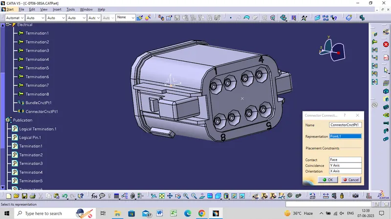
Define connector connection point (mating side)
Defining connector connection point at the mating side of the connector where representation is the center point, contact is the face, coincidence is the Y axis, and, orientation is the X axis.
c-2-174357-2
- Defining geometrical properties (points and axis system)
- Bundle entry side center point.
- Selecting two random points diagonally to get a center point.
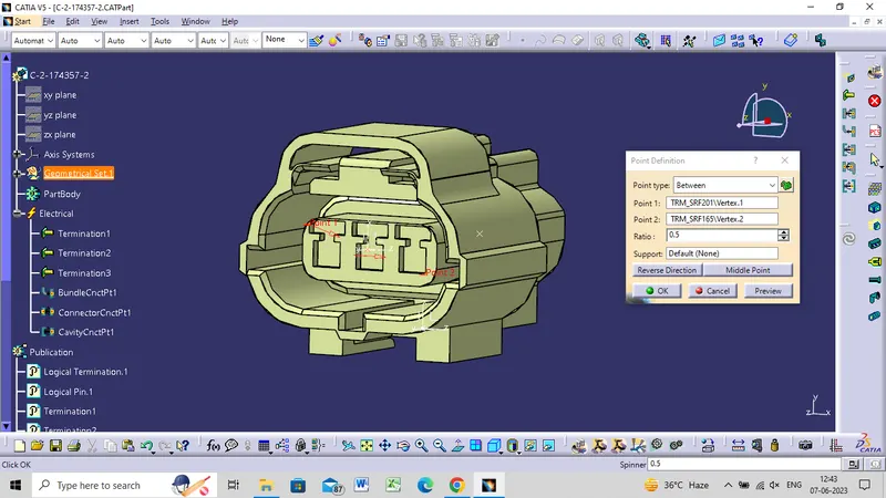
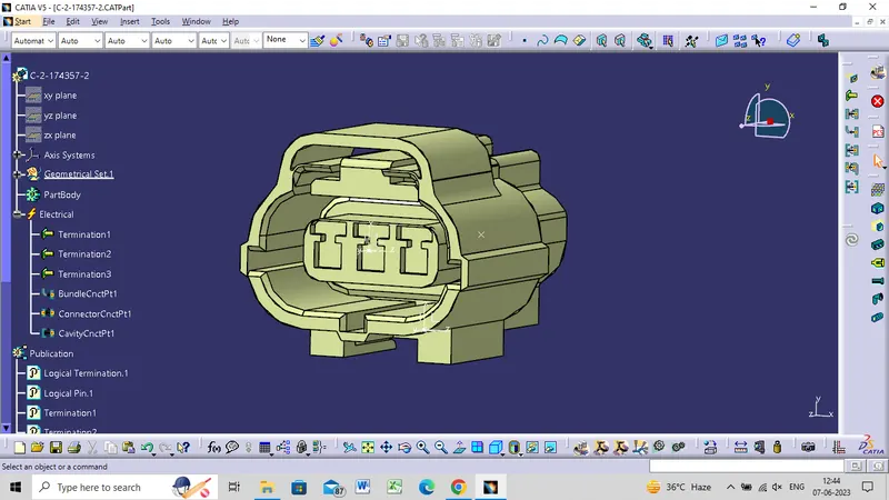
Mating side axis system
- Creating an axis system concerning the center point as the origin of the axis.
- The Y axis is directed at the mating direction, the X axis is directed towards the locking side and the Z axis is directed upwards.
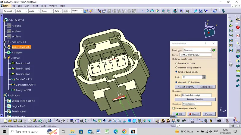
Selecting the edge of the cavity connection part to get a center point, under point type on the curve.
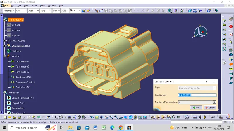
Electrical Part Design Workbench
- Define part as a connector
- Defining part as an electrical connector under Electrical Part Design Workbench. Selecting the number terminations 8.
Define bundle connection point (bundle/wire entry side)
Defining bundle connection point at the bundle entry side where, representation is the face, point as the center point, and initial condition also as the face.
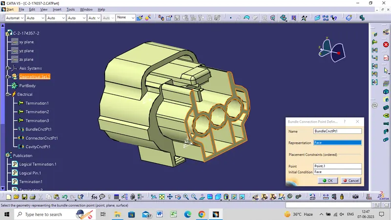
Define connector connection point (mating side)
Defining connector connection point at the mating side of the connector where representation is the center point, contact is the face, coincidence is the Y axis, and, orientation is the X axis.
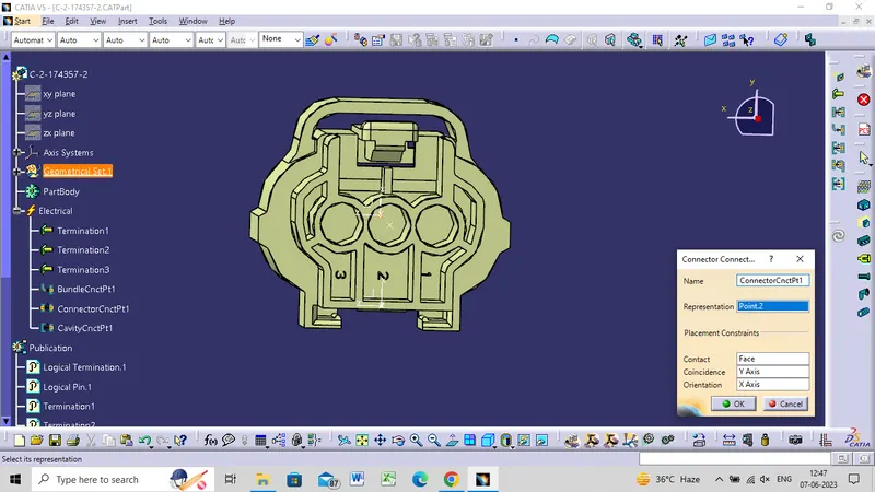
CLIP CONNECTOR
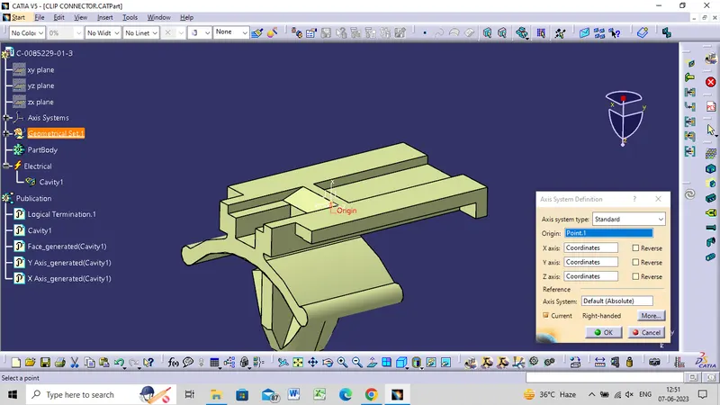
Mounting clip axis system
- Creating an axis system for the cavity, the origin is the center point, the Y axis is directed towards the insertion, the X axis is directed upwards and, the Z axis is directed to the side.
- The axis direction should follow the connector's cavity connection axis direction for proper mounting.
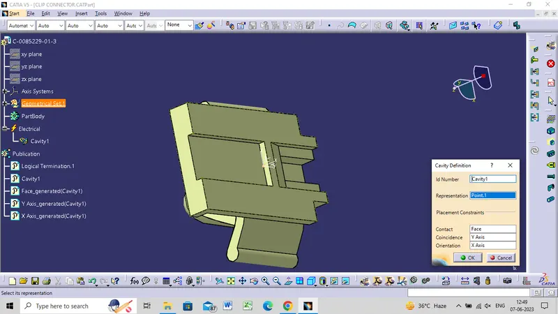
Electrical Part Design Workbench
- Define part as a Mounting Equipment.
- The clip is defined as electrical mounting equipment.
- Connect Electrical Devices
- The connector and connector clip are connected under the electrical assembly design workbench using connected electrical devices.