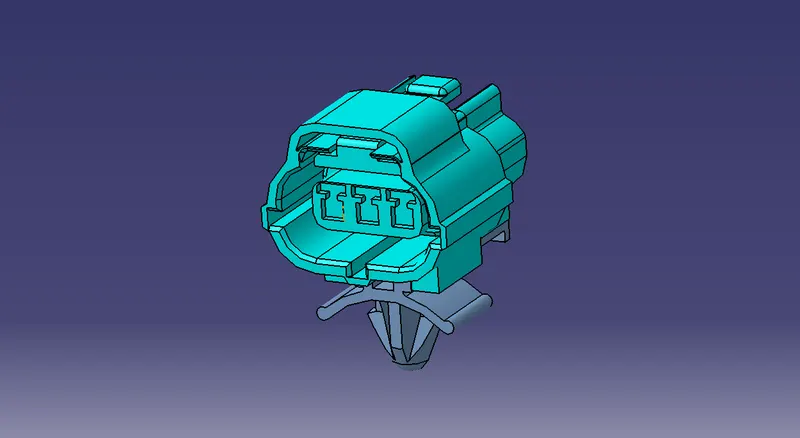
Wiring harness design in CATIA V5 - 3D modeling Week 2 Challenge
1. Deutsch DT06 – 08SA
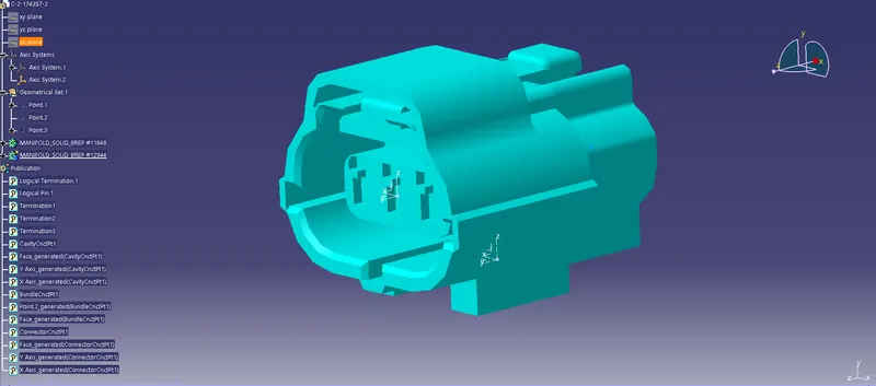
- Define Points in the Bundle section, Mating section, and Mounting Clip part in the part design workbench.
- After that create an Axis system at both the Mating and Mounting sections.
- Later, go to the Electrical part design workbench and Define the component as an Electric device in this case Define it as a connector.
- Now use the command 'define bundle connection point' for the connection points at the Wire Connecting area.
- Similarly, for Mating Point use the command 'define connector connection point', and for Mounting use the command ' Cavity connection point'.
- The above steps ensure that the component is an electrical device ready for virtual routing.
2. Tyco 174357-2
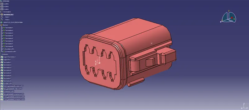
- Define Points in the Bundle section, and Mating section, part in the part design workbench.
- After that create an Axis system at the Mating sections.
- Later, go to the Electrical part design workbench and Define the component as an Electric device in this case Define it as a connector.
- Now use the command 'define bundle connection point' for the connection points at the Wire Connecting area.
- Similarly, for Mating Point use the command 'define connector connection point'.
- The above steps ensure that the component is an electrical device ready for virtual routing.
3. Tyco 85229-1
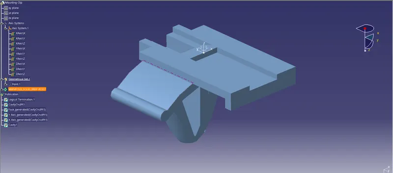
- Define the Point at the Mounting Clip part in the part design workbench.
- After that create an Axis system at both the Mounting sections which should be made referring to the axis system on the connector that is to be mounted.
- Later, go to the Electrical part design workbench and Define the component as an Electric device in this case Define it as a Mounting Equipment.
- Now use the command 'define Cavity' for the connection points at the Mounting area, as we have used the command Define Cavity Connection Point on the connector.
- The above steps ensure that the component is an electrical device ready for virtual routing.
Assembly of Electrical Devices