Wiring harness design in CATIA V5 - 3D modeling Week 2 Challenge
Wiring harness design in CATIA V5 -3Dmodeling Week 2 Challenge
Aim :
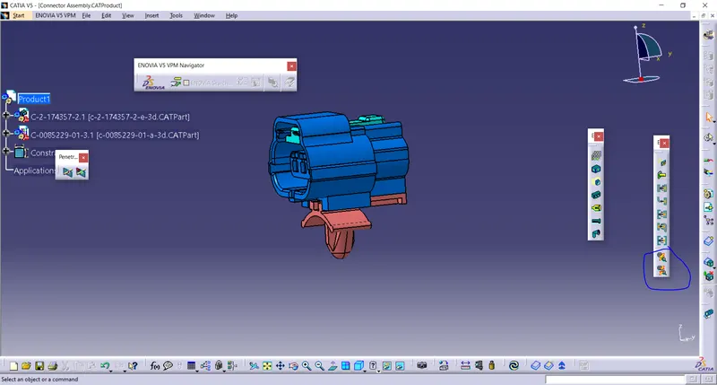
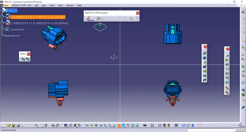
Download following Connectors and Connector clip cad data from given link & define ig as Electrical Connector using Electrical part design workbench. Define all the necessary properties to connectors & clip.
Introduction to Wiring Harness.
- Electrica Distribution System (EDS)
Elecctrical Distribution System basically deals with physically & Logical Architecture, Schematic Development, Power distribution , Wiring Harness Design wiring harness Components design of given electrical system.
- E&E Archetecture:
It is hoigh level lgical connectivity diagram represents the number of system, Sub- Systems and logical connectivity between them. It is extended to show the CAN network between different Electronic controlers.
- Logical Schemetics:
Logical schemetics is detailed design of E&E Archetecture which is extended to show the logical connectivitybetween different components & Controles of given sysyem, Sub Systems.
- Electrical Schemetics:
Electrical Schematics is detail design of logical schematics with describes the pin connectivity, Properties, Fusing distribution , Grounding distribution, Inter connects, wire properties, Circuite properties , specification of components etc. This is the end result of electrical core design of system and used as an primary input for harness developmet.
- Wiring Harness Topology:
Wiring Harness Topology is startegy to divide or split the harness between different pieces to acheive the best Manufacturability, Servicebility & Cost effective design.
- Wiring Harness Routing.
Wiring Harness Routing deals with desired path of wiring strategy of wiring harness into given environment by applying set of design rues & Industry best practices.
- Wiring Harness packaging.
Wiring Harness packaging deals with Fixing/Mounting Strategy of wiring harness routing to ensure the safe. Reliable & Durabulity of wiring by applying set of design rules & Industry best practices.
Vehical Electrical Distribution System ( EDS) Introduction:
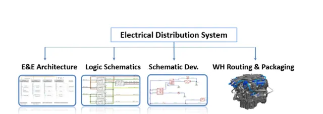
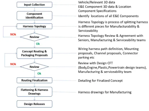
Typical Design Flow EDS System.
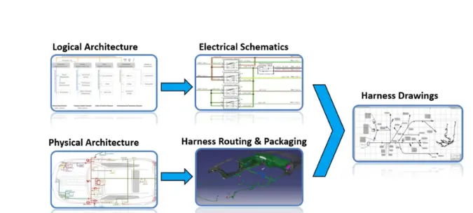
Wiring Harness Design Process:
Wiring Harness Assembly Structure - Connector Defination
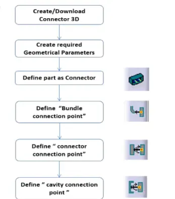
Wiring harness Assembly Structure - Connector Defination
Following Parameters are required to defined for any connector-
Geometry Parameters : Points & Co-ordinate system ( Axis)
Connector Connection Point : This point is used for the connection of one connector to another connector.
Cavity Connection Point: This point define where the harness bundle segment point will end when routed to the electrical connector.
Cavity Conection Point (Optional) : This point is used to define the connection of a connector Clip. This only applies to connectors which have the mounting features for a connector Clip.
Connector Connection CATIA V5:
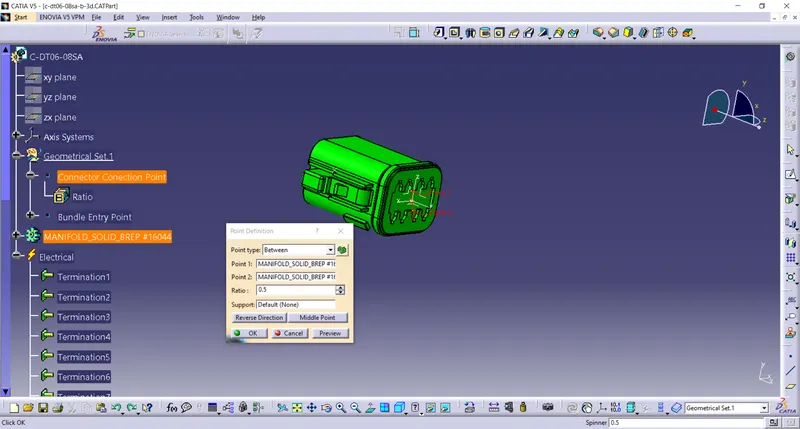
1. Deutsch Connection Point:
- Creat Mid Point on the contactface which will be normal to wire bundle insertation.
- Create Axis system with respect to the point which we have created and defining the axis direction as shown below.
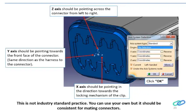
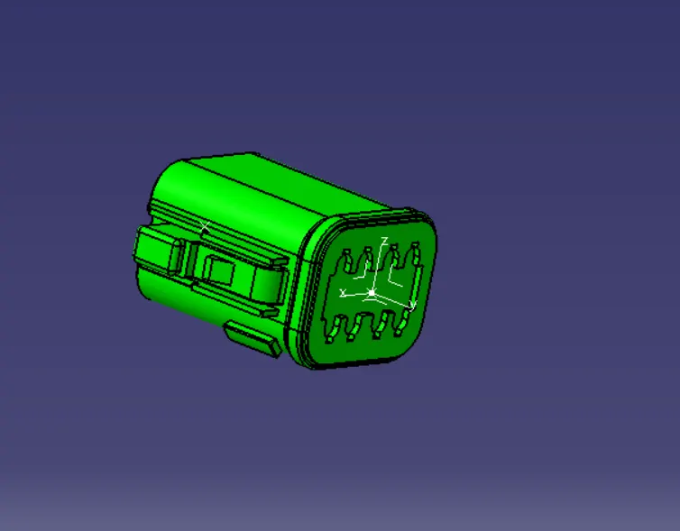
- Switch of Bundle Connection Point:
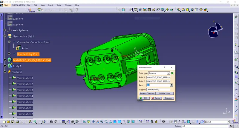
Switch of Electic part design
- Define the parts as connector in Catia, Give no of termination as 8 becouse we have 8 entry points for wire.
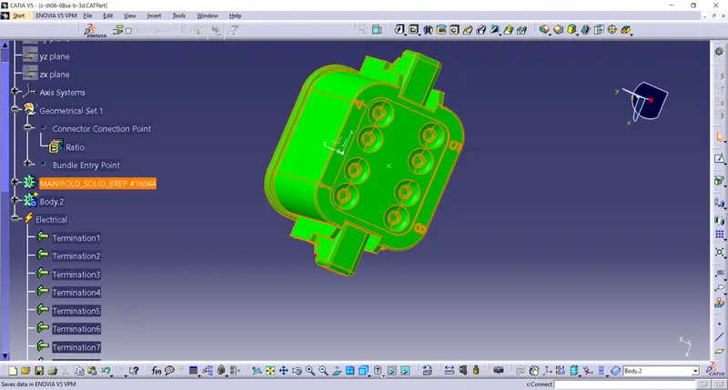
- Define Bundle Connection Point.
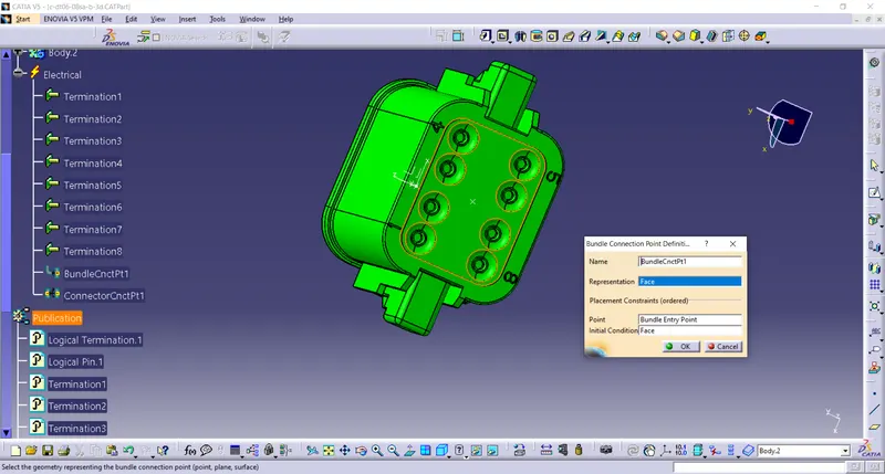
- Define Connector Connection Axis.
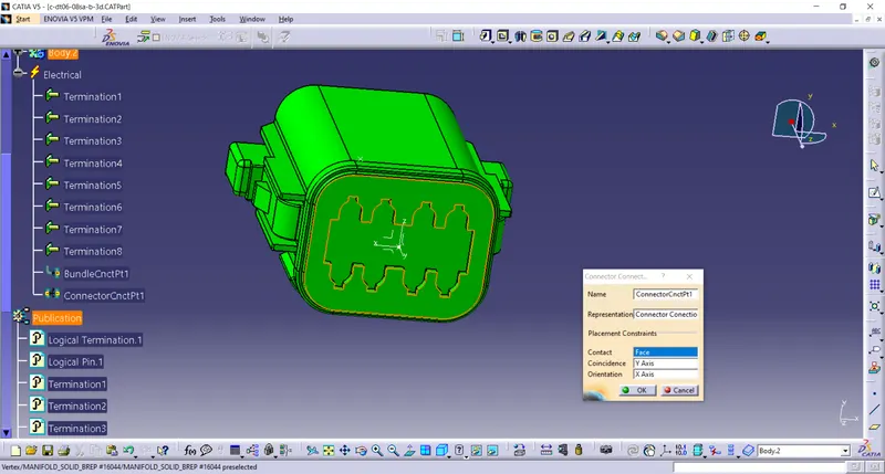
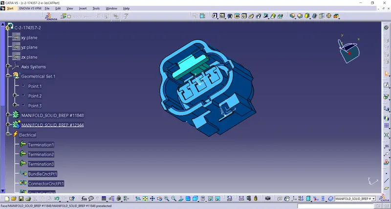
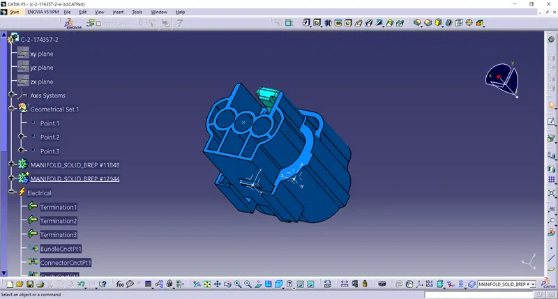
2. Tyco 174357-2
- Create midpoint
- creat Connector Conection Point.
- Create Connector Conection axis system.
- Create Cavity Conection Point.
- Create Cavity conection axis system.
- Switch to electric part design and define part as conector.
- Define conector conection point and Cavity conection point.
Electric Assembly Design
- Import Connector and cavty/ mounting clip.
- Select Defining Electric Connection.
- Select Cavity and then Connector.