Hood design-Week 2
Hood Design
Objective
To understand the design strategy and consideration that goes to under dsigning developig an automative hood to achieve maximum safety for everyone in and around the vehicle.
With this understanding an industry- standurd hood panel is to be designed which can very well be manufactured assembled. in other words. the design has to fallow DFM and DFA standards as well.
Software used: Siemens NX10
In this report, the flow of information will be follows
In this report, the fallow of information will be as fallows
- Understanding
- Design Consideration
- Design
- Draft Analysis
- conclusion
1. Understanding
Hood, which also goes by the term bonnet, mostly in the commonwelth countries is essentially a type of door that covers the powertrain and other vehicle propulsion system components such as drive belts, battery, fluid levels and lamp units in the frontal region of an automobile .
Aside from being a hinged cover to enine proiding easy acces to maintainance and Repair.
Hood is one of the other major closure system in a vehicle and is fundamentaly a reinforced skin with many design quality and safety regulations.
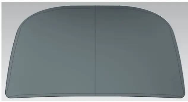
Hood may come with several subcomponents, but the two most important ones are the outer and inner panels. The inner panel serves as a structure for the vehicle to dissipate and channels shock waves at the event of a crash While the outer panel serves more as an asthetic for theautomobiles overall pesentaton and to channel airflow over the vehicle . Hence , both require critical precision as well as a dedicated strategy right from the design conceptalization to the production steps.
The initial design goes through iterative design modification based on structural analysis such as fatigue analysis and crash analysisto name few before it sees the light of the day.
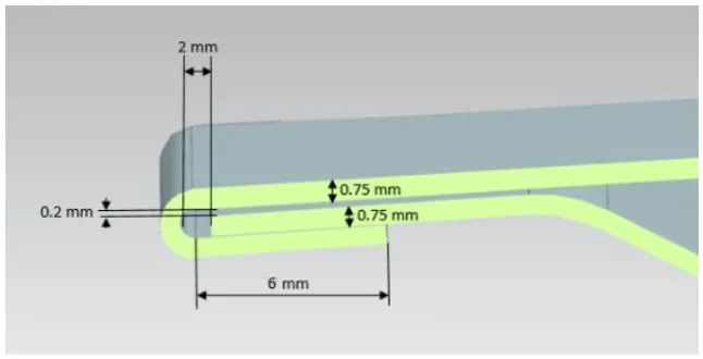
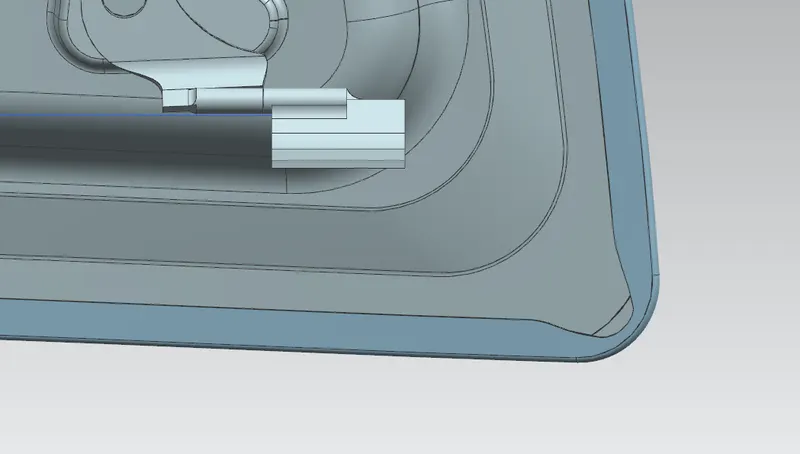
Once the design for the two subcomponents is finalized. the manufacturing process begins panel is generally manufactured by the deep drawing process. Once manufacgured, the outer and inner components are umited to form one umit by one or combination of several types of joining methods such as hemming, riveting, gluing, and spot welding to name a few. In this project, hemming was utilized to join these twocomponents. Hemming is performed after the parts have been deep drawn, trimmed, and flanged. It involves foding folding of he outer overap portion around the inner panel and pressed using 'hemming rollers to maintain a consistant surface joining.
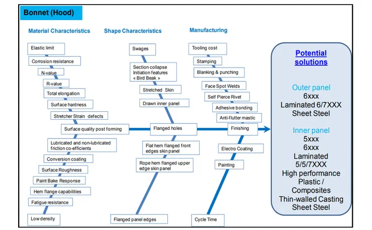
Fig,(a). Desired characterestics and manufacturing techniques aranged in a herring-bone diagram
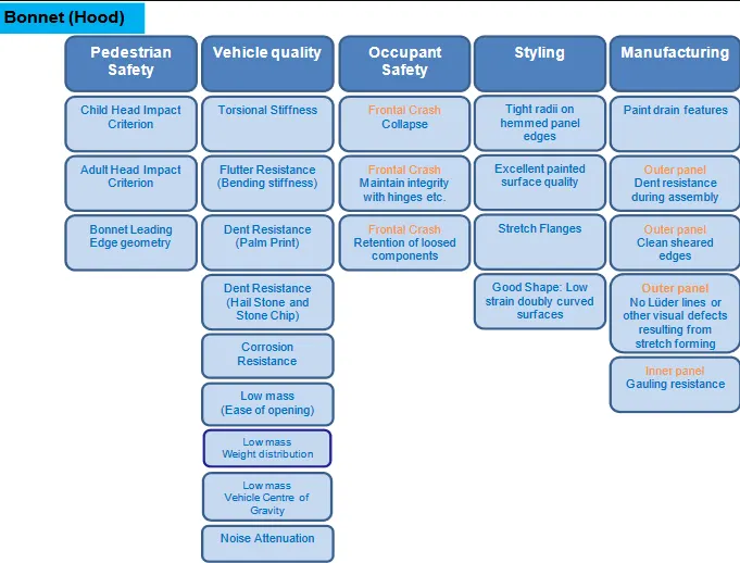
Fig.(b). Design Boundary Condition for Bonnet.
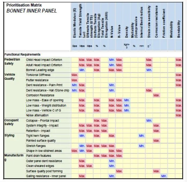
Fig.(c). Design Prioeitisation Matrix
The Designing of the inner and outer hood panel was performed with the below- presented specification
Data to be used:
Hood thickness Information
- Outer panel thickness= 0.75mm
- Inner panel thickness= 0.75mm
- Reinforcemet thickness= 1.5mm
Master sketch
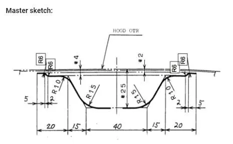
Fig.(d). Master Section and specification
Upon designing the initial structure based on the master section, embossing was performed to strenth the struture as well as to integrate channels to direct shock flow and dissipate maximum energy away from the cabin. With successful designing of these channels using the process of embosing, latchand hinge placements are designed for attachment of this structure to the vehicle. Once the structure for the inner panel is prepared. reinforceent is provided to componsate the strength drop which occured due to the inclusion of latch and hinge placement. at this stage , the NVH eam also contrbutes to implimenting major design changes and the inclusion of components to reduce vehicle vibration and noise controle.
Aport from hemming, the center region of the inner panel structure is kept in contact with the outer panel using mastic sealants. Mastic sealents are rubberzed components placed between the outer and inner panel to provide annexed contact. these sealants help maintain the outer panel aesthetically pleasing as well due to the absence of welds, nuts or bolts in the process of consoldation.
2.Design Consideration
As discussed in the earlier section, the hood plays a critical safety function in an automobile. not only for the occupants of the vehicle but also for the pedestrian. Hence, a lot goes in while designing the hood and must be complaint with the standards and considerations. In this project, the European new car assessment programe, popularly know as EuroNCAP, was followed to understand the consideration and standards one must fallow while designing a hood. EuroNCAP plays on instrumental role in raising awarness on safe and effective design for the pedestrian. It programs and develops test series and rating systems for accessing design safety for pedestrisn during impact with a vehicle. The tests aree generally executed for vehicle hit speed at around 40 km/h and covers the pedestrian body interaction with the vehicle upon collision.
Bellow represented chart through light on same of these considerations for the frontal crash of a vehicle with pedestrian.
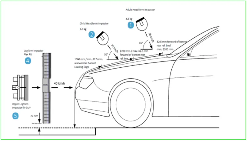
Fig.(e). Pedestrian crash dummy placement Child and Audult
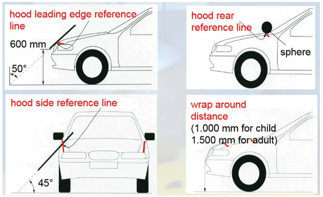
Fig.(f). Head Impact Region
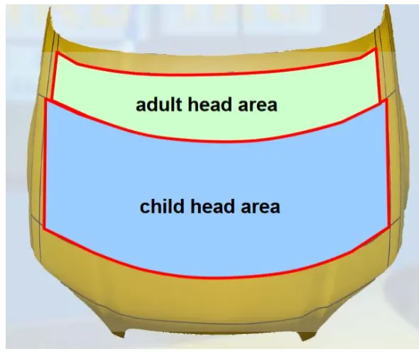
Fig.(g) Impact Area for Child and Audult Head
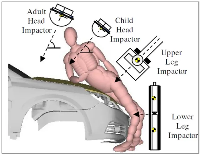
Fig.(h). Body- Bonnet Interaction
As we could see the impact region. basded on these impact regions the thickness of he hood at those regions are redused to allow safter landing and lower impact. Upon impact of the pedestrian, the hood in those regions should absorb and dissipate the energy allowing deformation and hence collapsing. which in turn would result in a lower impact on ghe pedestrian.
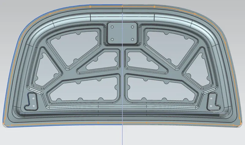
At the same time, the impact on the vehicle should be channeled outside the vehicle to safeguard the occupants from severe injuries. Based on these considerations, the inner panel should be embossed with startegized channels and empty cut-outs to allow for maximum absorption of such impacts.
With this understanding, the below- provided design was executed using Siemens NX10.
3. Design
Inner panel
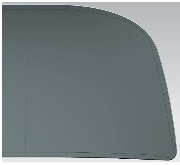
Outer panel
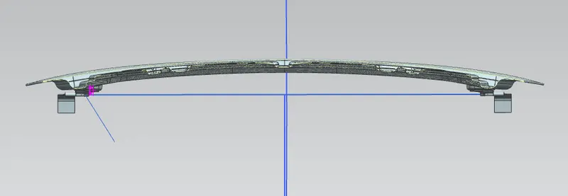
Cross Section
Hemming
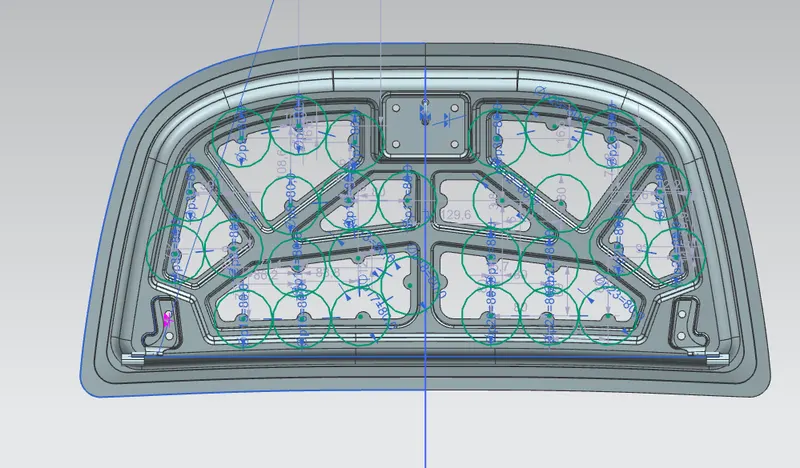
Mastic Scealant Regions
Mastic sealants generally have an influence area of about 80mm
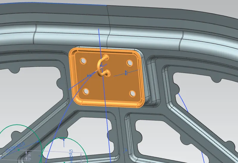
Stricker
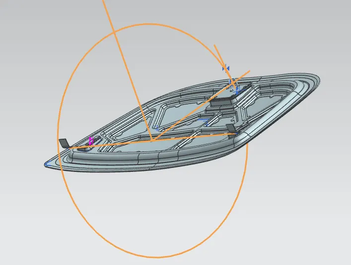
Position of Hinge and Striker
The hinges should be usually placed on both sides of the hood in such a way that the fits exactly in to the hole provided.
To ensure this the following conditions are fallow:
1. both the hinges shold be on the same axis.
2. The center of the stricker's circuler trajectory should be always perpendiculerto the axis.
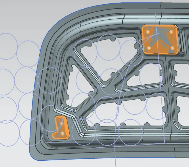
Reinforcements( in amber- Yellow)
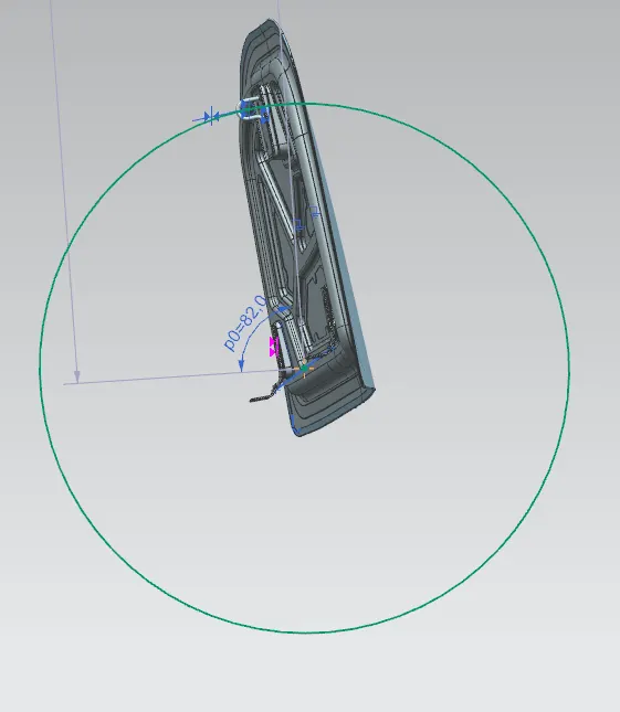
Hood opening and Closing Trajectary
The trajectory for opening and closing is consideres to be proper when the striker's axis is coincidental with the hood center axis. the perpendicular line from this axis is selected from the hinges on either side.
Shock Flow
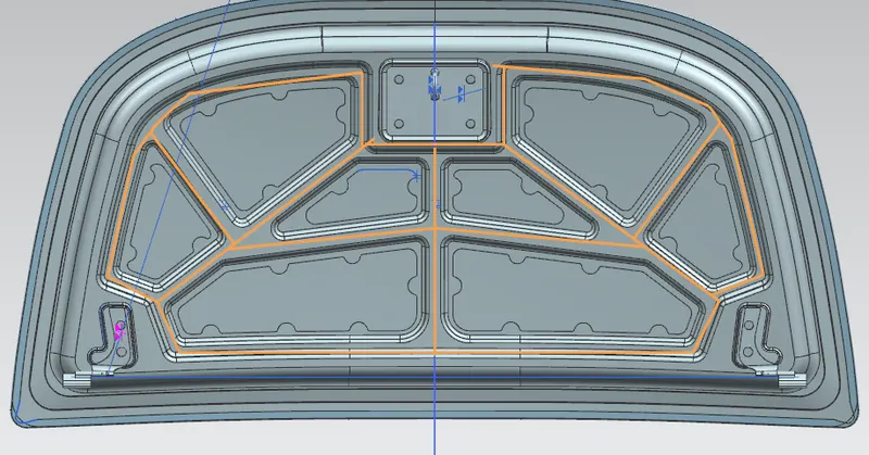
The embossed channels were designed to direct the impact force towords outside of the structure
4. Draft Analysis .
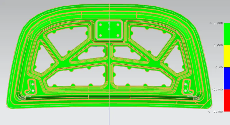
Once the design was ready, the complete hood was analyzed for manufacturability. using the Draft Analysis function from siemens NX, it could be seen that the designed part can manufactured without any dificulties.
5. Conclusion
With the completion of the design and analyzing it for successful manufacturabiliy, we can conclude that this can be utilized for a vehicle. Also the design was exected under the EuroNCAP safety standards and hence satisfies hood safety both for occupants and the pedestrians.