Wiring harness design in CATIA V5 - 3D modeling Week 2 Challenge
Aim:
Download following connectors & Connector clip cad data from given link & define it as Electrical Connector using Electrical Part design Workbench. Define all the necessary properties to Connectors & Clip.
- Deutsch DT06 – 08SA ( https://www.te.com/usa-en/product-DT06-08SA.html)
- Tyco 174357-2 (https://www.te.com/usa-en/product-2-174357-2.html?source=header-match)
- Tyco 85229-1 – (https://www.te.com/usa-en/product-85229-1.html?q=85229&source=header)
Step 1: Download all necessary given connectors and clip from te.com, stp file and start working on them one by one on CATIA V5.
1 DT06 – 08SA:
- Download DT06 – 08SA stp file into the Catia V5 After that geomatrical set the place the point for Mading side Connector connection point& wire entry side bunndle connection point after that provided Axis system in mading side .
- So for bundle connection point we create a mid point on surface where terminal bundles is going to attach, so we create the mid point on that surface.
- for cavity connection point we give a mid point on the mating side of connector and define it as connector connection point.
- Now define the connector by command on electrical part design and give no. of termination as 8 because there are 8 bundles segment.
- Now define the bundle connection point by giving the face of point as referance and point as bundle entry point and initial condition as face normal to point.
- provided the axis system for connector connection point side Y-axis for mating direction,X-axis for locking direction,Z-Axis for Right to left Direction.
- After that define the Electrical equipment system for connector look like this:

Tyco 174357-2:
- Download the Tyco 174357-2 stp file into catia v5.
- Point place into mating side for Connector connection point.
- Point place into wire entry side for Bunndle connection point.
- Point place into Lockmechanciam side for cavity connection point.
- provided the axis system for connector connection point side Y-axis for mating direction,X-axis for locking direction,Z-Axis for Right to left Direction.
- provided the axis system for Cavity connection pont side Y-axis for mating direction,X-axis for locking direction,Z-Axis for Right to left Direction.
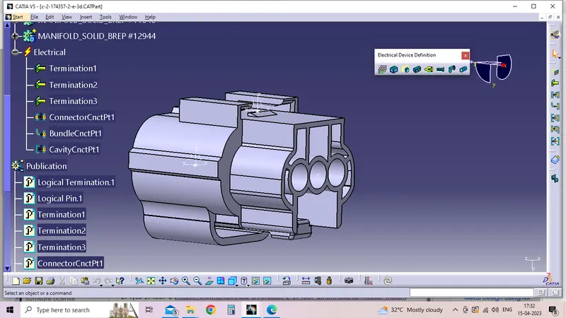
- Now define the connector with its 3 terminals and define bundle point and connector connection point same as we did in previous connector
- defined electrical equipment system coverted into Connectors;
Tyco 85229-1
- Download the Tyco 85229-1 stp file in catia v5 .
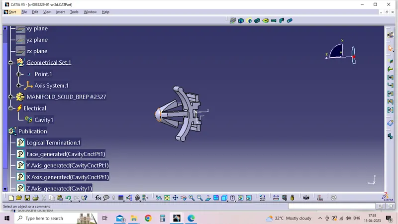
- Point place for Cavity.
- provided into Axis system for Mating with cavity connection point Y-axis for mating direction,X-axis for locking direction,Z-Axis for Right to left Direction.
- Difine that equipment system as working as a Clip.
Electrical assembly Work bench.
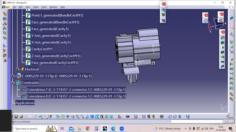
Connector clipTyco 85229-1& connector Tyco 174357-2 import into Electrical assy work bench difine Electirical connect devices perfectly constriants, connect the cavity connection point and the cavity point which is represented using axis systems .
Catloge Creation:
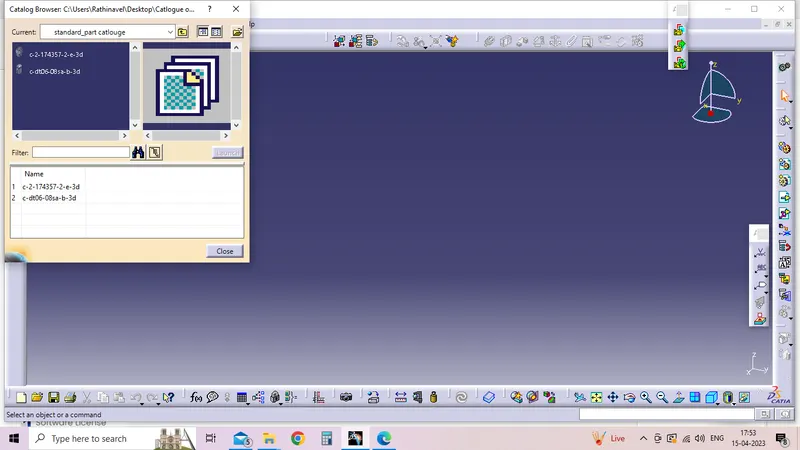
Difine the location of the catlouge after go to the catlouge editor oprn the location after add family for standard parts storage into the catlouges.