Wiring harness design in CATIA V5 - 3D modeling Week 2 Challenge
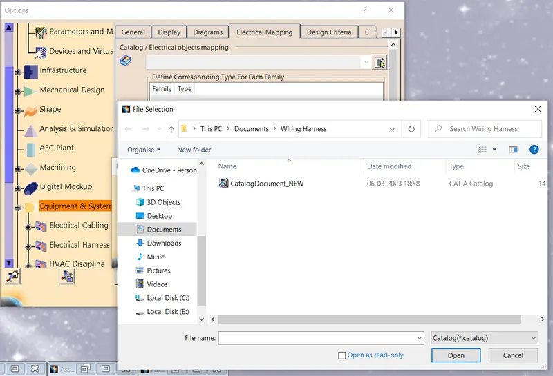
I created Catalog and browsed it to get the same CAD files in a Electrical Part Design.
This we get after adding CAD files in Catalog.
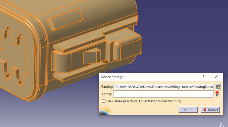
Connector defination in Catia v5
Deutsch DT06 – 08SA
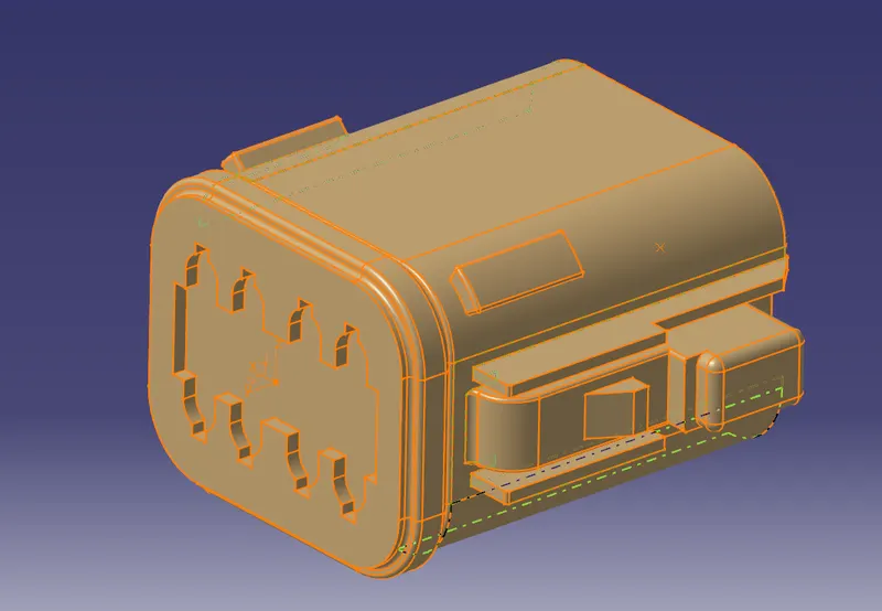
First we see what are the faces that are goingto connect to a Bundle harness and other connector.
Accordingly we give the electrical connectivity.
We take the CAD in Part Design and give geometrical parameters.
We make sure the Yaxis is always in the direction of mating. X directing towards the locking system and z according the former two.
so, we Declare the CAD as a Connector using Define Connector in Electrical Part design.
Then we select Define Bundle connection point and select the face and point accordingly.
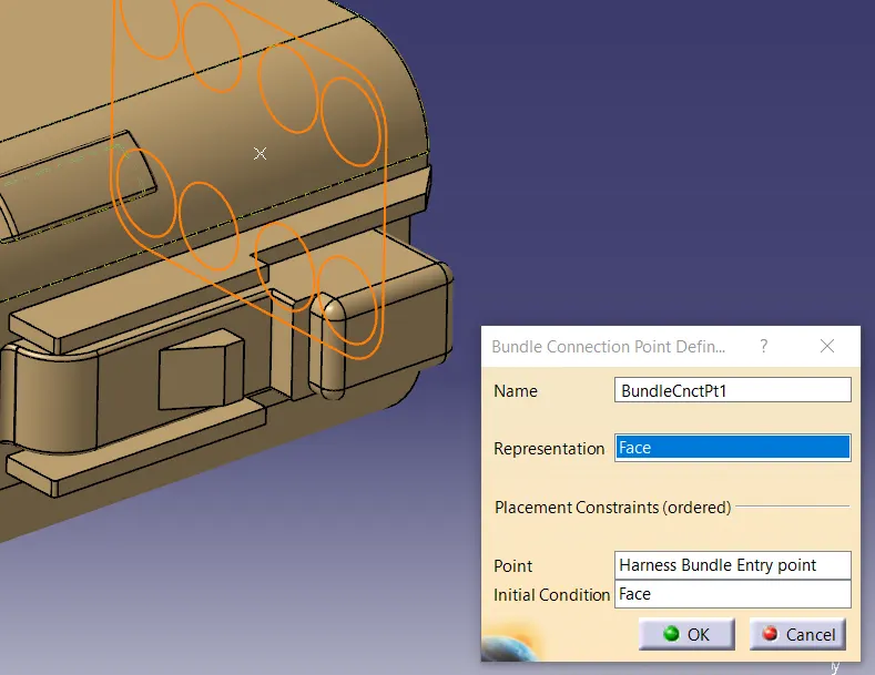
Then we define Connector Connection POint.
Here we select the point , face and axis for constraining the same.
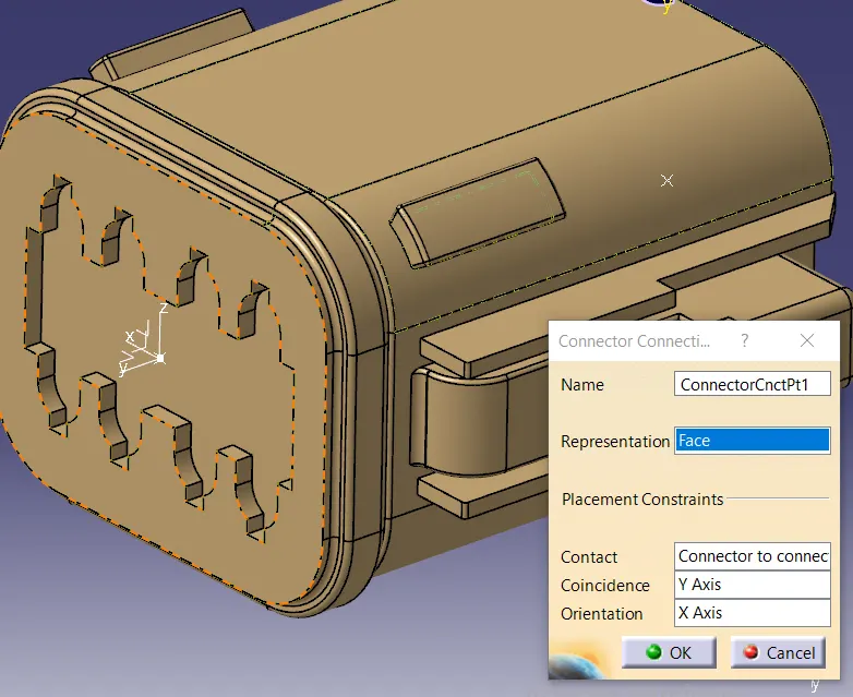
Tyco 174357-2 and Tyco 85229-1(Mating Pin)
Taking the CAD and giving them point , Axis geometrical parameters.
The overall Procedure is
- Create midpoint
- create Connector connection point
- create Connector connection axis system
- create cavity connection point
- create cavity connection axis system
- Switch to Electric part design and define part as connector
- Define Connector connection point and cavity connection point.
Here we have a locking pin surface for contrain. So we give the axis system same as the surface on the cavity.
as shown,
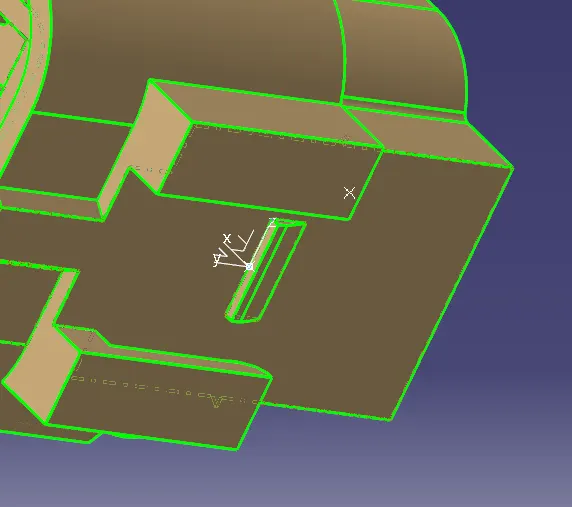
For Pin,
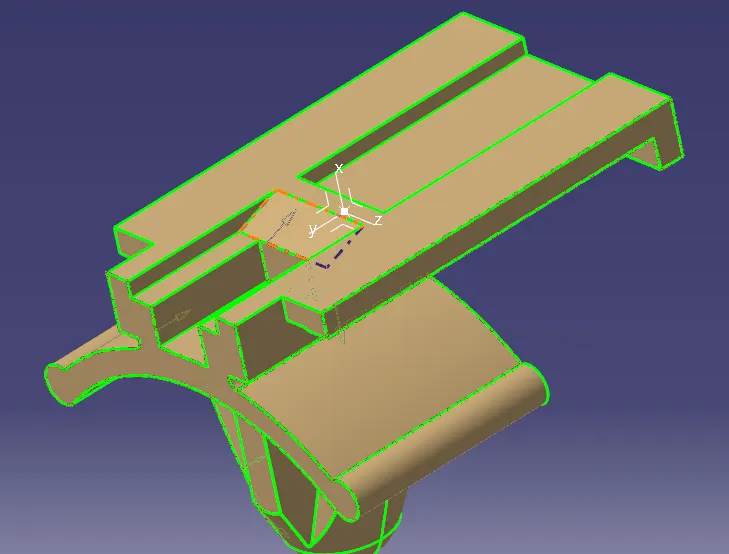
- Create midpoint
- create cavity connection point
- create cavity connection axis system and orientation should be same as in connector
- Switch to Electric part design and define part as Mounting Equipment
- Define cavity connection point
Assembly.
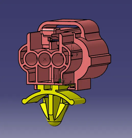
In assembly we constriant using Connect Electrical Devices similar to how we do in solid. Here we use point and axis.