Wiring harness design in CATIA V5 - 3D modeling Week 2 Challenge
OBJECTI VES:
- In this challenge you will be working on downloading the files form the te.com website and then defining the parts electrically and further creating a catalogue for the components
Answer:
- Following files of Deutsch DT06 – 08SA, Tyco 174357-2 and Tyco 85229-1 has been downloaded from te.com website.
Creation of Points and Axis system for Connector DT06 – 08SA:
- Create a point from part work bench using point command.
- Then choose point type as between and select 2 points and choose middle point option to create a point.
- From this option we have to create bundle connection point and connector connection point.
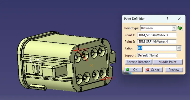
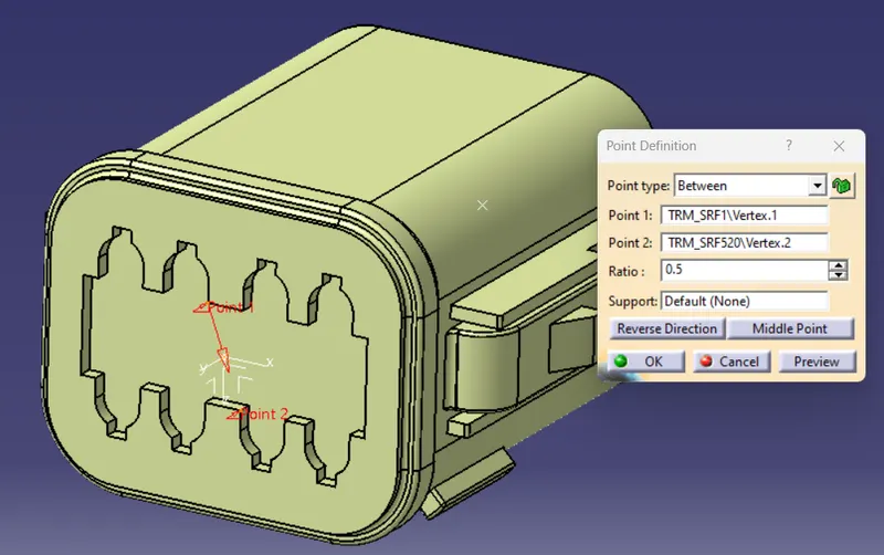
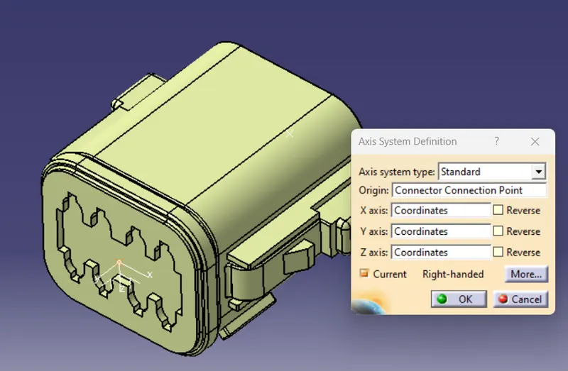
- Axis system has been created using axis system command from part work bench
- Then choose axis sytem type as standard and selct the orgin as connector connection point.
- And adjust the coordinates of X axis pointing in the direction of locking mechanism, Y axis pointing towards the front face of the connector.
Creation of Points and Axis system for Connector Tyco 174357-2:
- Create a points using point command from part work bench.
- Then create bundle connection point, choose point type as circle/sphere option and select the arc.
- Then create connector connection point, choose point type as between and select 2 points and choose middle point option to create a point.
- Then create cavity connection point, choose point type as on curve and select the line of the locking pad and choose middle point option to create a point.
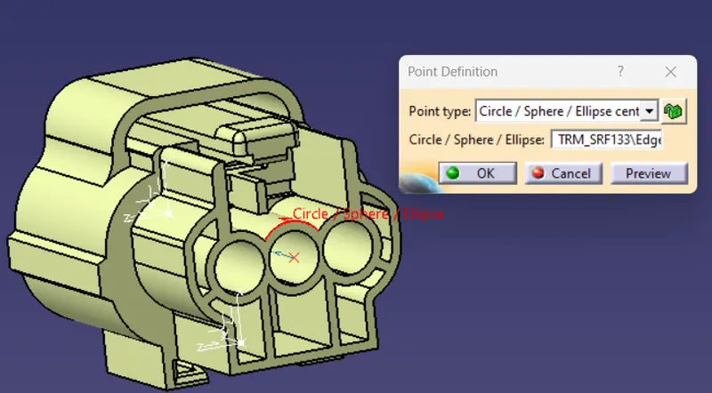
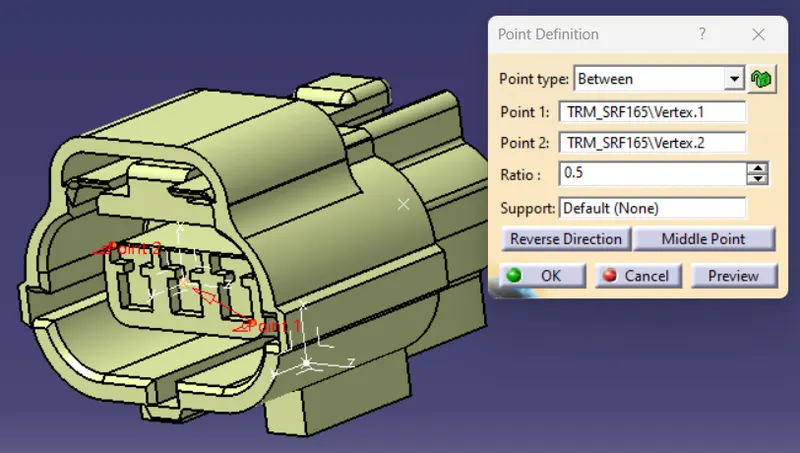
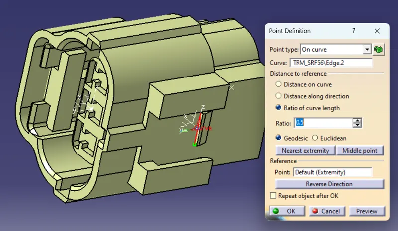
- Connector and Cavity Axis system has been created using axis system command from part work bench
- Then choose axis sytem type as standard and selct the orgin as connector connection point.
- And adjust the coordinates of X axis pointing in the direction of locking mechanism, Y axis pointing towards the front face of the connector.
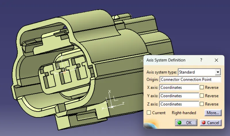
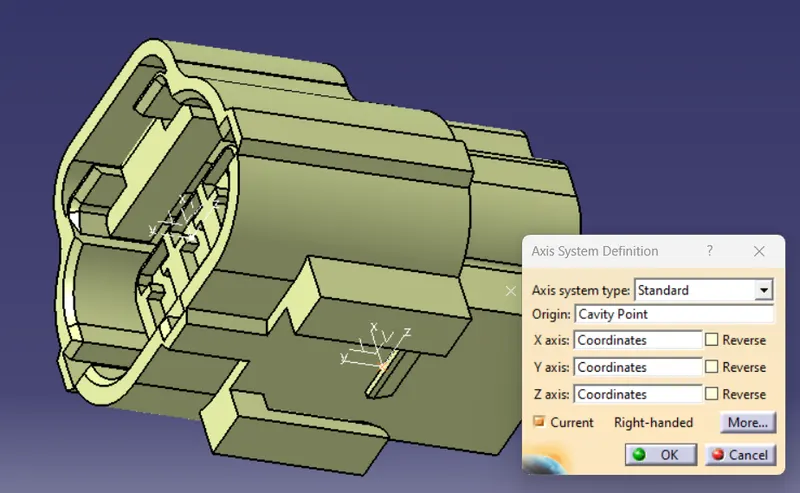
Creation of Points and Axis system for Connector clip Tyco 85229-1:
- Create a points using point command from part work bench.
- Then for creating cavity connection point, choose point type as on curve and select the line of the locking pad and choose middle point option to create a point.
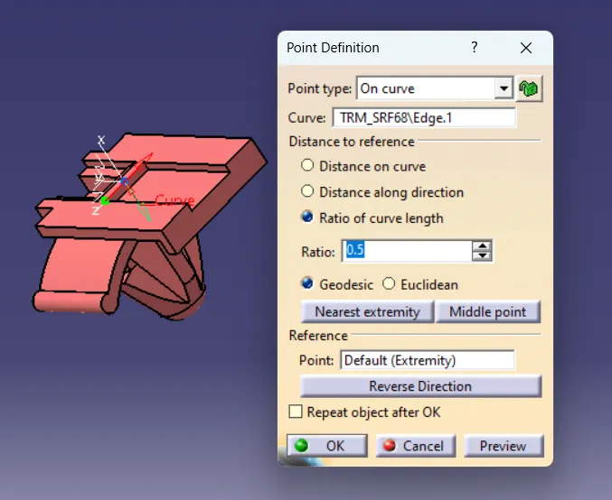
- Connector clip Cavity Axis system has been created using axis system command from part work bench
- Then choose axis sytem type as standard and selct the orgin as connector connection point.
- And adjust the coordinates of X axis pointing in the direction of locking mechanism, Y axis pointing towards the front face of the connector.
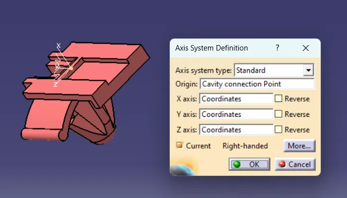
Electrical definition of connectors and Connector clip using CATIA V5:
- It is define by using electrical part design work bench
- Choose define connector option and choose the part, then popup window will open there choose the type of the connector, part number and put the value in number of terminations and click ok. For this the connectors terminations will created.
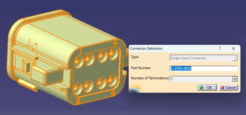
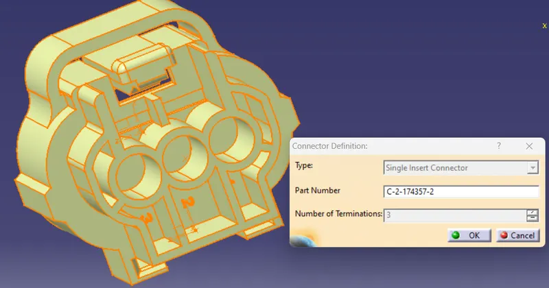
- After define the connectors next step is to define bundle connection point of the connectors.
- For this choose bundle definition point command and choose the connectors.
- Then coose the name, then choose the representation face, then choose the bundle connection point and choose initial condition face.
- Then click ok to create bundle definition point.
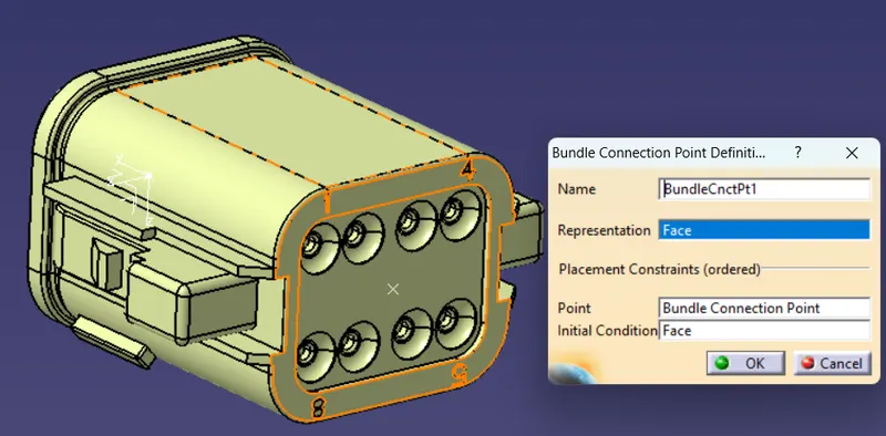
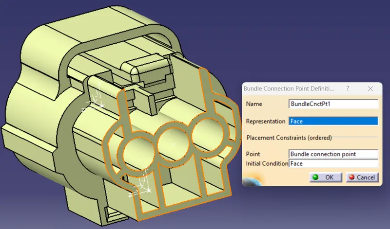
- After define bundle connection point next step is to define connector connection point.
- Open define connector connection point option and choose the connector.
- Then popup window will open there put the name of the connector.
- Then select the representation as connector connection point, choose face as contact, choose Y axis as coincidence, choose X axis as Orientation.
- Then click ok to define connector connection point
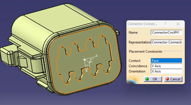

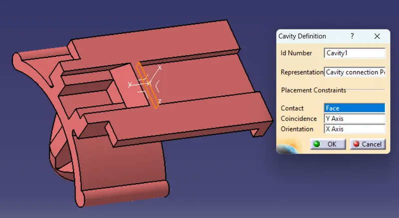
- After define connector connection points next step is to define cavity connection point of the Tyco 174357-2 connector and Tyco 85229-1 connector clip.
- Open define cavity connection point option and select the connector/clip.
- Then choose the name, then choose the cavity point in the representation option.
- Then choose face as contact, then choose X axis as coincidence and choose X axis as Orientation.
- Then click ok to define cavity connection points of connector and clip.
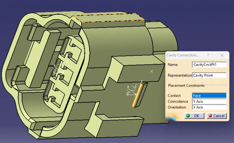
Catalogue Creation:
- File-new-catalog document to open the new workbench
- Then open add family option to create catalog in desired location and family.
- Then for adding the connector in the catalogue there is a option called store device in electrical part design workbench
- Then choose the catalog and choose the family group and click ok.
- Then the connector is added in the catalog
Conclusion:
Files has been downloaded from the te.com website and then defining the parts electrically and further creating a catalogue for the components has been completed and attached in the file.
Thanks