Wiring harness design in CATIA V5 - 3D modeling Week 2 Challenge
UPLOADING:
- Download the required component as 3d model in suitable format form the open-source websites like te.com.
- Import the downloaded model into Catia.
PART DESIGN WORK BENCH:
- Open part work bench.
- Create a new geometrical set the electrical geometry data
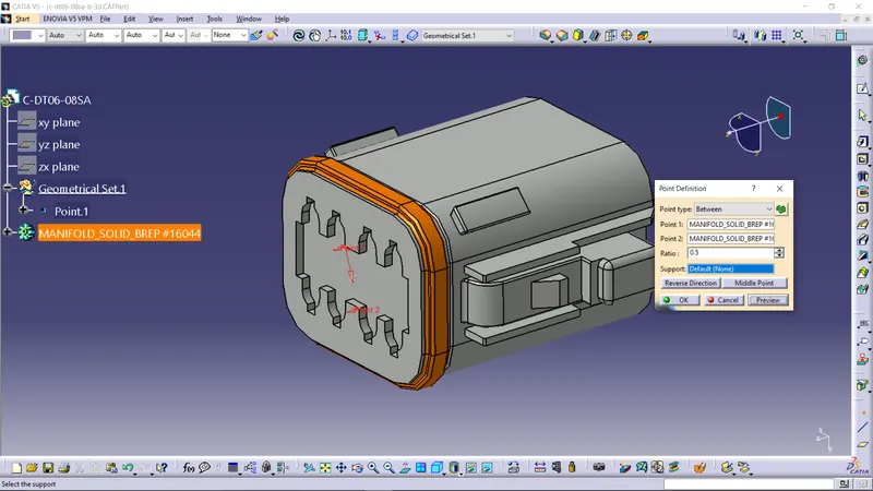
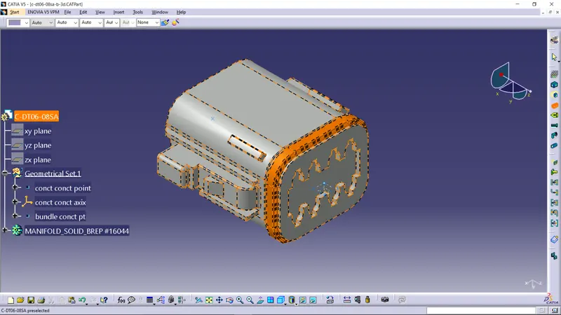
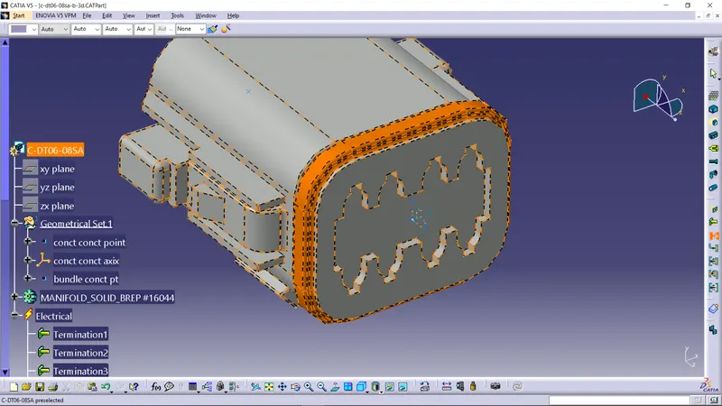
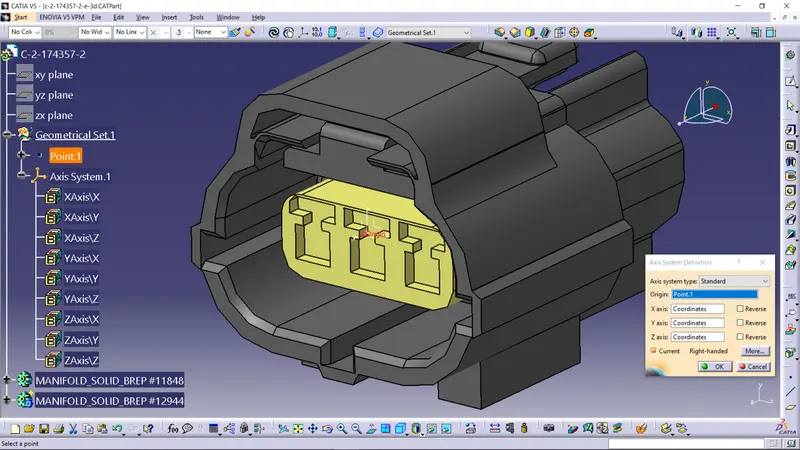
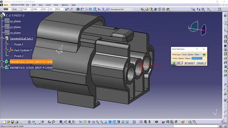
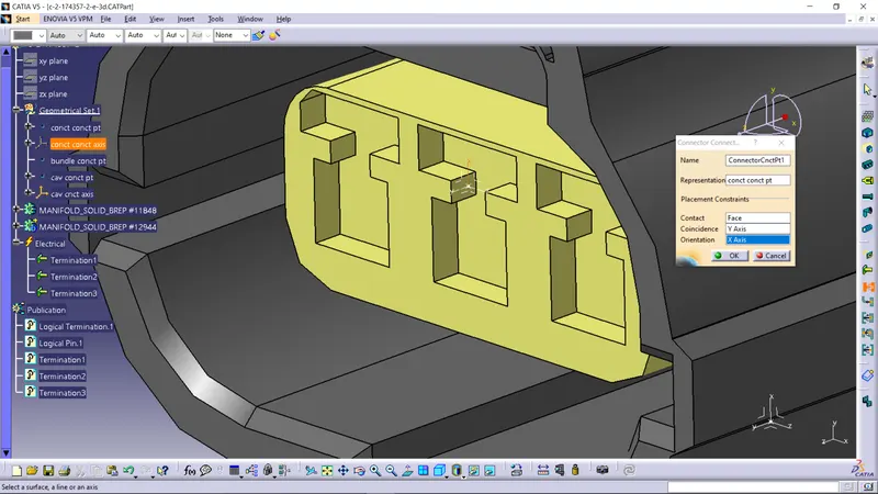
- Connector connection point: Create a point on the centre of the connector mating face.
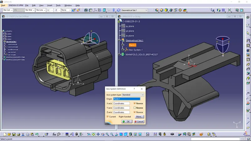
- Connector connection axis: Create an axis system with connector connection point as origin, y-axis directing toward matting connector attachment direction and x-axis directing the clip of the connector.
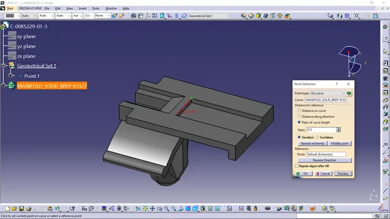
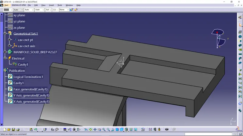
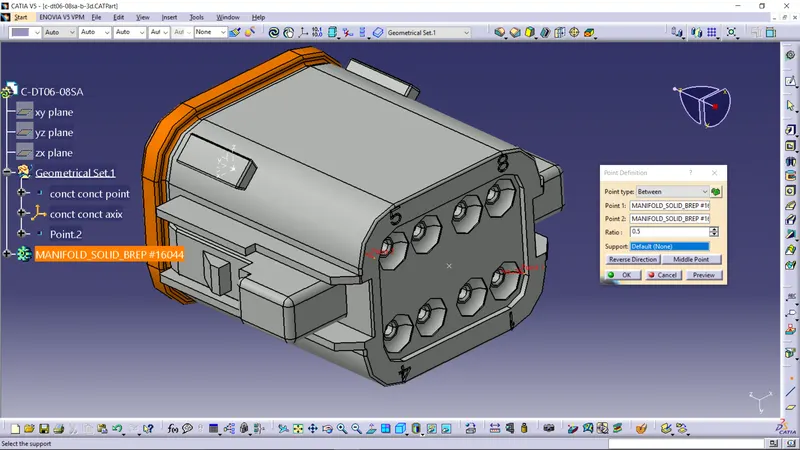
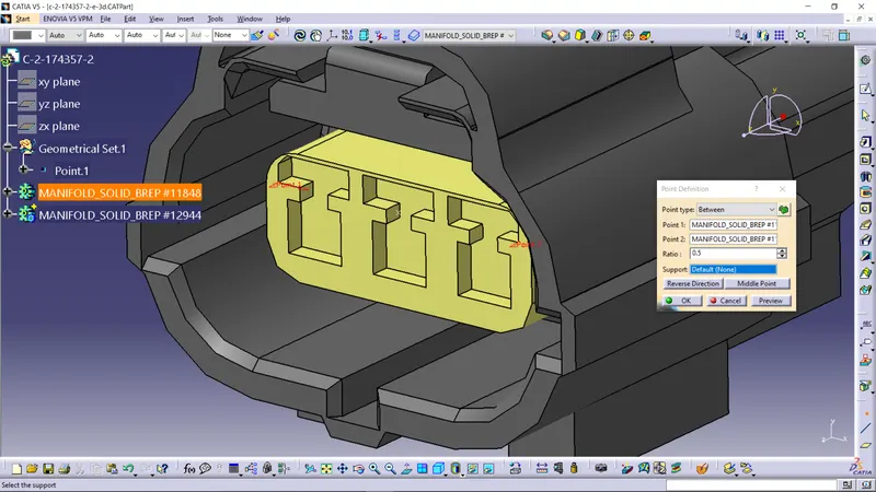
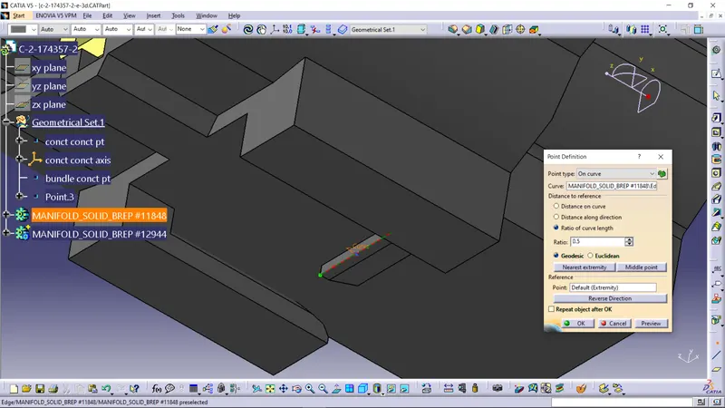
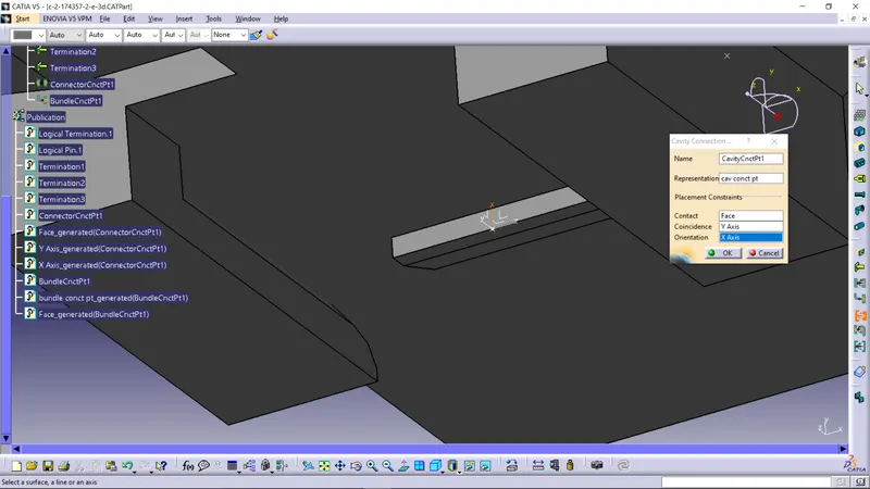
- Cavity connection point: Create a centre point on the any edge of the face that contacts cavity and clip.
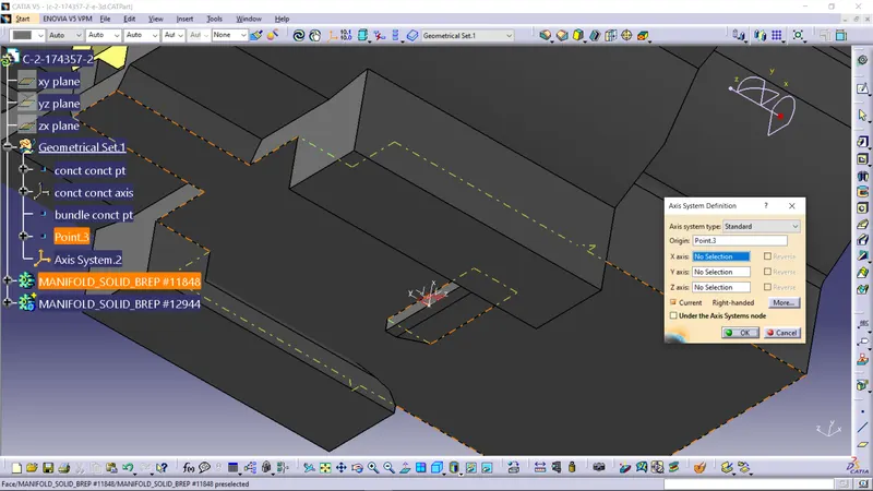
- Cavity connection axis: Create an axis system with cavity connection point as origin, y-axis directing the direction of sliding of the clip and x-axis or z-axis directing the connector for orientation. This should direction of the x or z axis should be same as the clip.
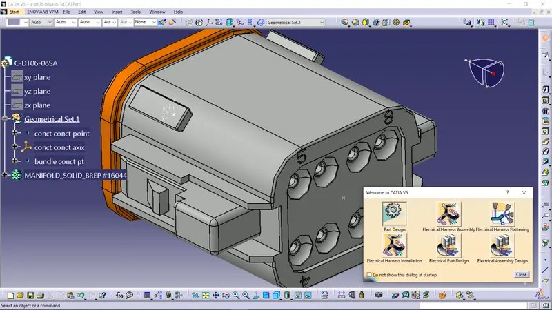
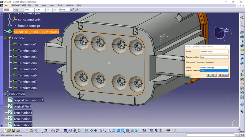
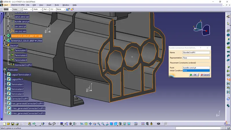
- Bundle connection point: Create a point on the centre of the bundle connecting face.
- Provide appropriate names for the point and the axis.
ELECTRICAL PART DESING WORKBENCH:
Open electrical part design workbench.
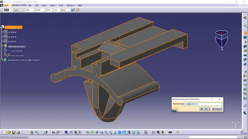
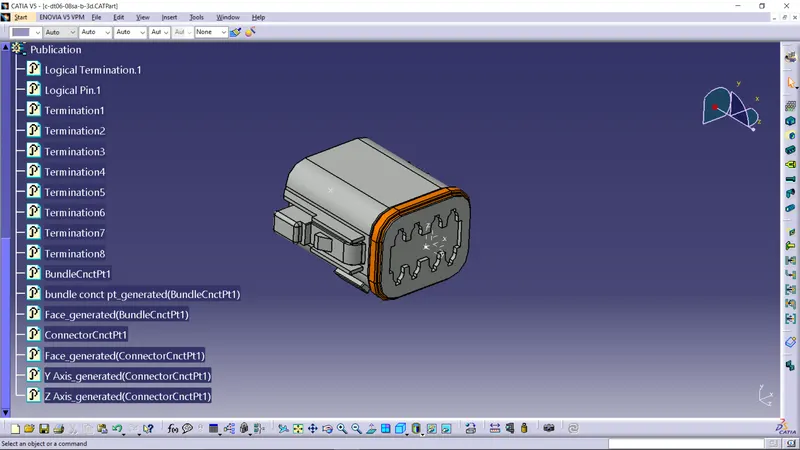
Select the Define support tool form the toolbar and click on the component to define it as a supporting or clamping component. This will be represented in publication branch of the tree.
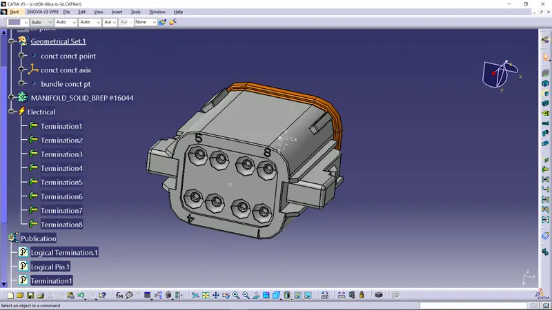
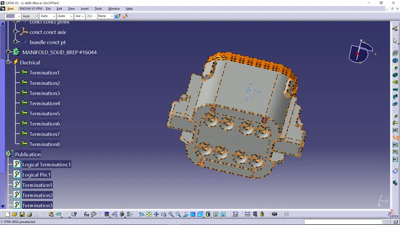
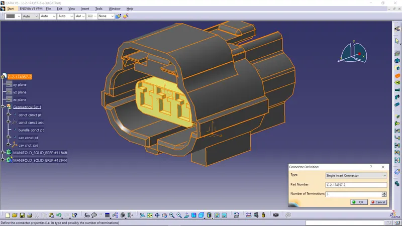
Select the Define connector tool from toolbar and click on the component to define it as electrical part. Choose the connector type and correct number of terminals in the component and click OK. This will create the terminal list in the newly opened electrical branch of the tree and in the publication branch.
Define Bundle definition point: Select define bundle connection point tool from toolbar and click on the component which opens a bundle connection point definition dialog box. Choose the bundle matting face as representation, bundle connection point as point, and same bundle matting face as initial condition and click OK. This will be represented in the Electrical branch and the publication branch of the tree.
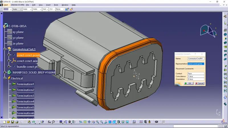
Define Connector connection point: Select define connector connection point tool from toolbar and click on the component which opens the connector connection point definition dialog box. Choose the connector connection point as representation, mating face as contact, y-axis as coincidence and z-axis as orientation. The orientation axis choose as same axis for the matting connector. This will be represented in the Electrical branch and the publication branch of the tree.
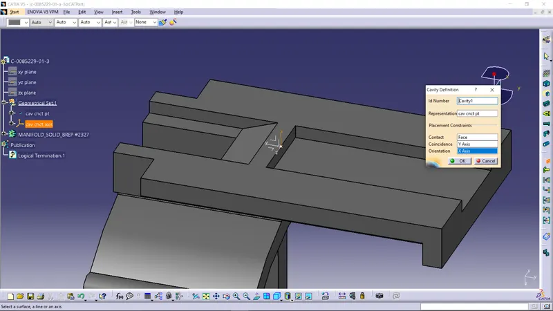
Define Cavity connection point: Select define cavity connection point tool from toolbar and click on the component which opens the Cavity connection point definition dialog box. Choose the Cavity connection point as representation, contacting face as contact, y-axis as coincidence and x or z-axis as orientation. The orientation axis should choose as same axis for the connector clip or clamp. This will be represented in the Electrical branch and the publication branch of the tree.
Define Cavity: Select define cavity tool form toolbar and select the support component which opens a cavity definition dialog box. Choose the Cavity connection point as representation, contacting face as contact, y-axis as coincidence and x or z-axis as orientation. The orientation axis should choose as same axis for the connector clip or clamp. This will be represented in the Electrical branch and the publication branch of the tree.
Deutsch DT06 – 08SA:
Tyco 174357-2:
Tyco 85229-1: