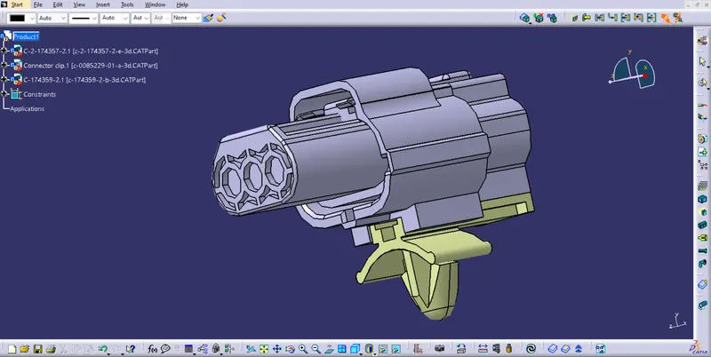
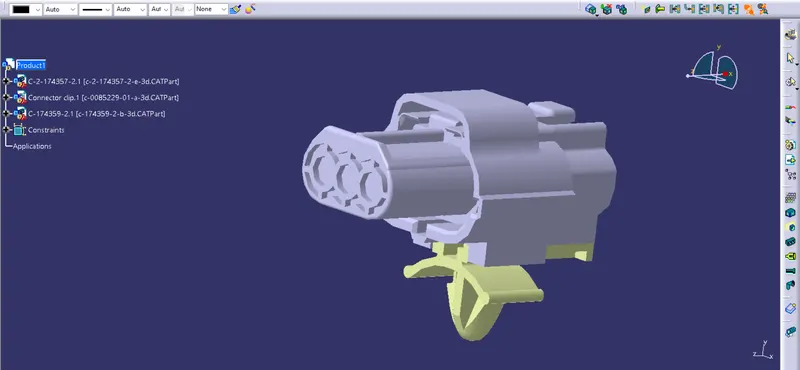
Wiring harness design in CATIA V5 - 3D modeling Week 2 Challenge
Aim - Define connectors and connector clip as electrical connector and provide all necessary properties to it
Objectives -
- Download Cad models.
- Making catalogs for connectors.
- Define it as Electrical connectors in electrical part design workbench.
- Define all necessary properties to connectors and clip.
Catalog making -
- A catalog is a CATIA V5 document that keeps a list of references to other CATIA parts and features.
- In a wiring harness it means that we can store a set of electrically defined CAT parts(like connectors, COT_Tubes, clamps,clips etc.) in a document and insert into product assembly whenever they are required.
Click on File > New > In List of Types : Catalog Document , a small window like below pops up where the highlighted blue
coloured selection (Catalog Document) has to be selected.
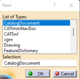
New window is pops up
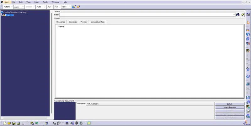
Click on add family in chapter tab
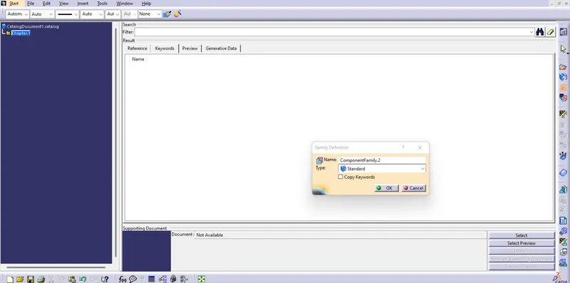
Provide name and its type and save it
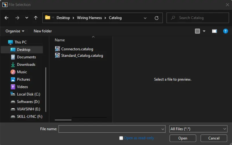
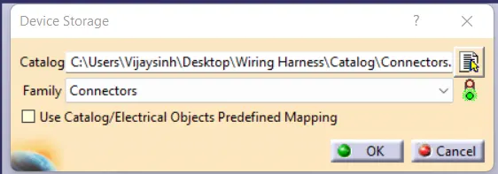
Connector
Following paramters are required to define any connector
- Geometry parameters - Points and co-ordinate system
- Connector connection point - This point is used fot the connection of one connector to the another connector.
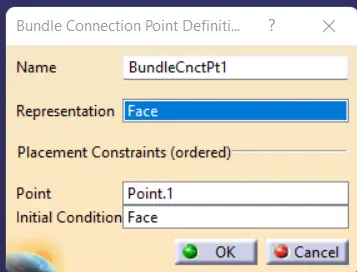
- Harness bundle entry point - This point defines where the harness bundle segment point will end when routed to the electrical connector.
- Cavity connection point - This point is used to define the connection of a connector to a connector clip. This only applies to connectors which have the mounting feature for a connector clip.
Procedure-
- Insert cad model in catia v5.
- Create a point on face of coonecting side
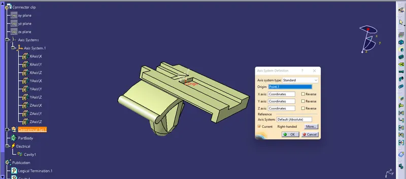
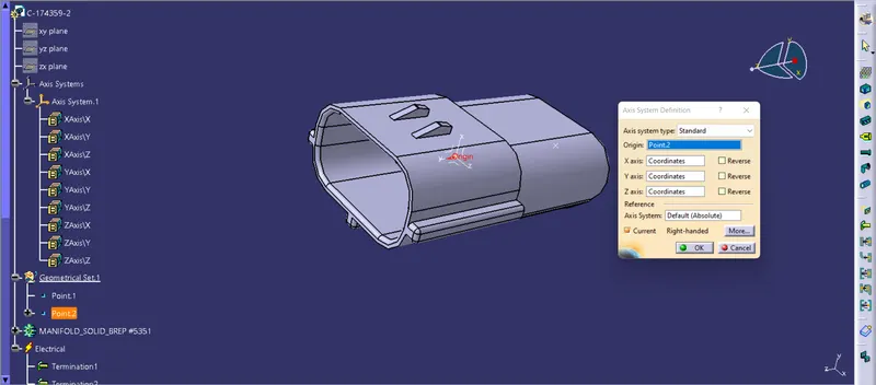
- create a axis system on this point - The connector axis system should be on the front face of the connector attached to a point on 0,0,0 coordinate. The point shold be on the conter of the front face as this point is used to connect the connector to the anothe electrical component.
- X should be pointing the direction towards the locking mechanism of clip
- Y axis should be pointing towards the front face of the connector (Same direction as the harness to the connector
- Z axis should be pointing across the connector from left to right.
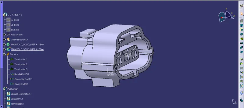
Create a point on other side for bundle entry
click on define connector and select the model
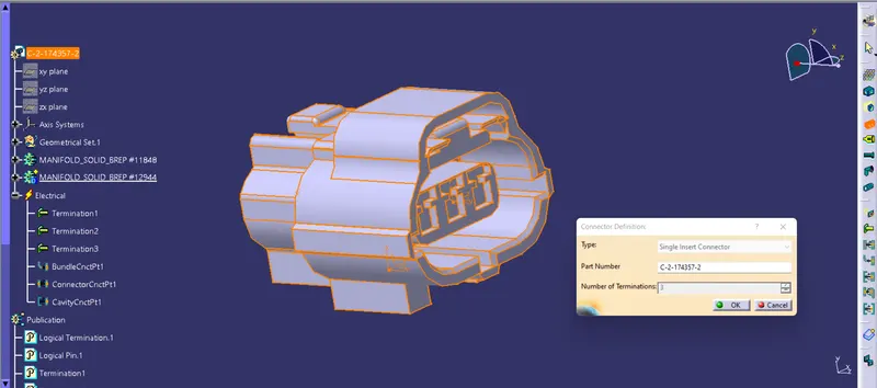
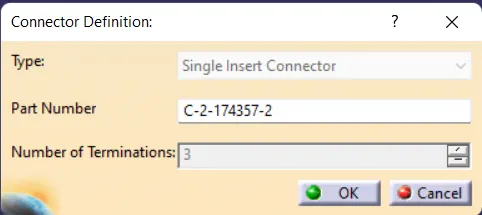
Define bundle connection point -
Define connector connection point

Connector Cavity axis
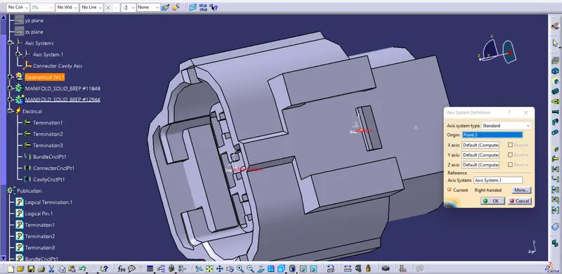
Connector Clip -
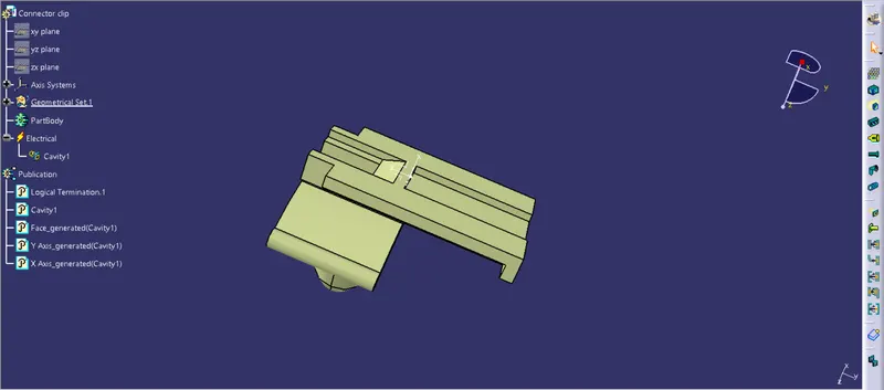
Axis System for connector clip
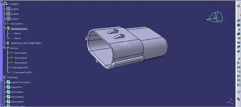
Male Connector -
Axis System for male connector
Assembly -
Paste all component in it
Click on connect electrical devices and select appropriate component and constraints