Wiring harness design in CATIA V5 - 3D modeling Week 2 Challenge
Electrical connector definition in catia.
In this challenge the mentioned connectors are downloaded.
They downloaded as the STP format. These files are opened in catia.
Then these files are saved as CAD part using that part design workbench.
Then we have to create two points using the reference point tool for both bundle connection point and also connector connection point.
After inserting the points for the connector connection point we have to define a coordinate system so that the counterpart of the connector can be aligned properly.
So in some connectors we have to create another point and the coordinate system For the cavity connection point also.
After creating all the points and all the coordinate system we have to change the workbench into electrical part design.
In the electrical part design we have to define the part as a connector with giving the number of terminations available.
Now we have to define the the bundle connection point or the Bundle entry point using the bundle connection point tool.
The bundle connection point do we have to select the face which should be normal to the incoming bundle and also the point of attachment between the connector and the bundle.
after defining the bundle connection point we have to define the connector connection point.
To define the connector connection point we have to use the connector connection point tool.
Once selecting the tool we have to click on the body of the connector so that the books will be visible.
In the box we have to first select the plane which is normal to the incoming connector, then the point of contact between those two connectors and also the perpendicular direction which is the Y direction and the orientation direction which is the X direction.
If the connector is coming with hey cavity connection attachment so that the connector can be attached to the body panel of the automotive, we had to define the cavity connection point using the cavity connection point tools.
We had to define the the point onto which the cavity is to be connected and the phase normal to the cavity and also the perpendicular direction which is the wide direction and the orientation direction which is the X direction.
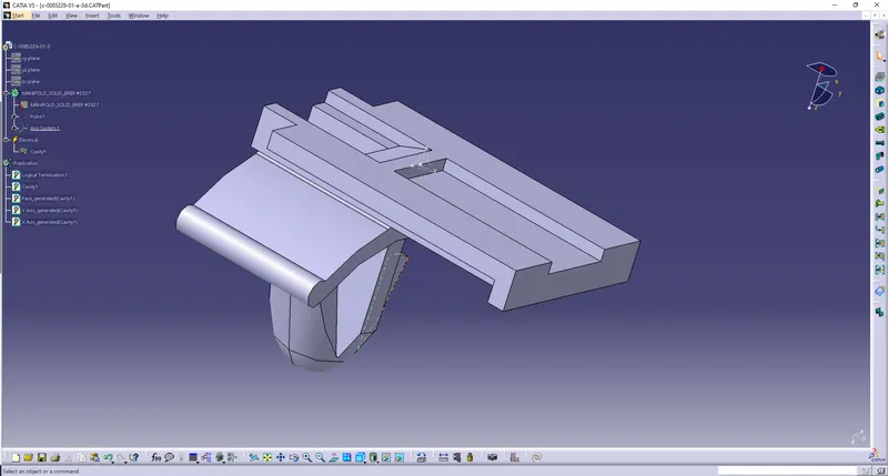
The theater component which is to be downloaded is a clip.
For a clip we have to define it as a mounting equipment.
For a clip we have to define the cavity using define cavity tool.
All of these procedures are done for the three connectives given
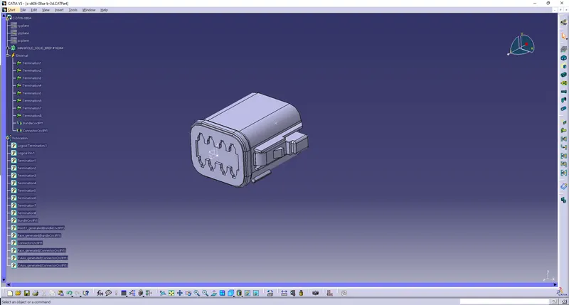
For part 1-Deutsch DT06 – 08SA
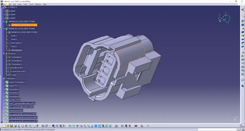
For part 2-Tyco 174357-2
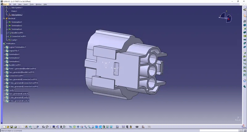
For part 3-Tyco 85229-1