Wiring harness design in CATIA V5 - 3D modeling Week 2 Challenge
Aim: Define it as Electrical Connector using Electrical Part design Workbench. Define all the necessary properties to Connectors & Clip.
Conector defination:
Geometry Parameters:- Point & Co-ordinate system (Axis)
Connector Connection point:- This point is used for the connection of one connector to another connector.
Harness bundle entry point - This point defines where the harness bundle segment point will end when routed to the electrical connector .
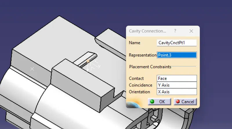
Cavity connection point ( Optional ) - This point is used to define the connection of a connector a connector clip . This only applies to connectors which have the mounting feature for a connector clip
Connector 1:
First, I Downloaded the model from the given link.
Deutsch DT06 – 08SA ( https://www.te.com/usa-en/product-DT06-08SA.html)
Open Mechanical Design -> Part Design in part design given a Center point with help of Between point.
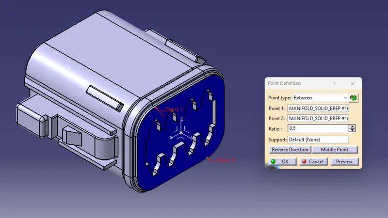
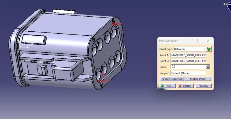
Given Axis System connector connection side.
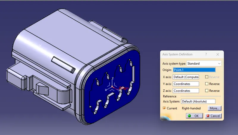
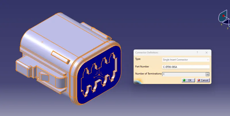
Part Changed to Electrical part design Then model defines as an 8-terminal connector.
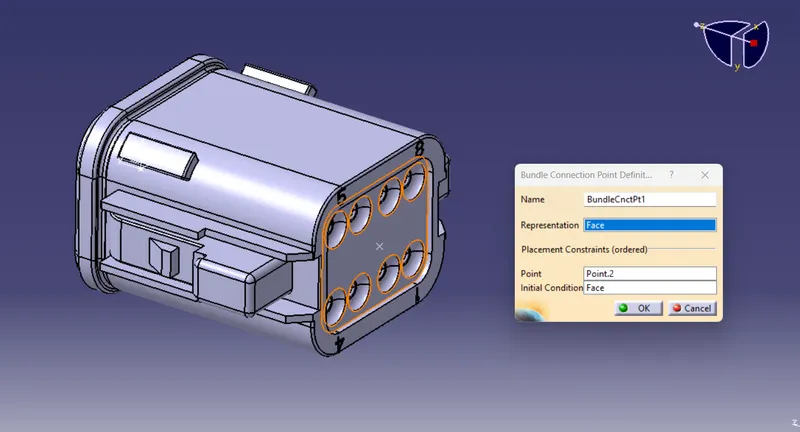
The Bundle connection point is defined on the Bundle connector side.
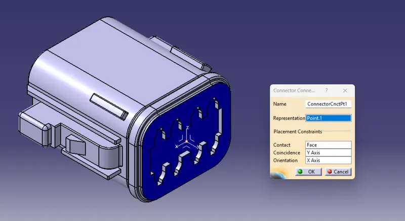
Then connector connection side is defined as the connector connection point.
Connector 2:
First, I Downloaded the model from the given link.
Tyco 174357-2 (https://www.te.com/usa-en/product-2-174357-2.html?source=header-match)
Open Mechanical Design -> Part Design in part design given a Center point with help of Between point.
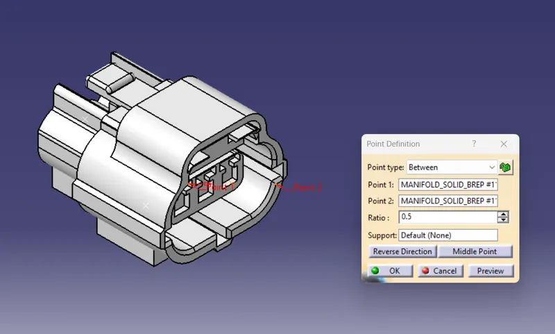
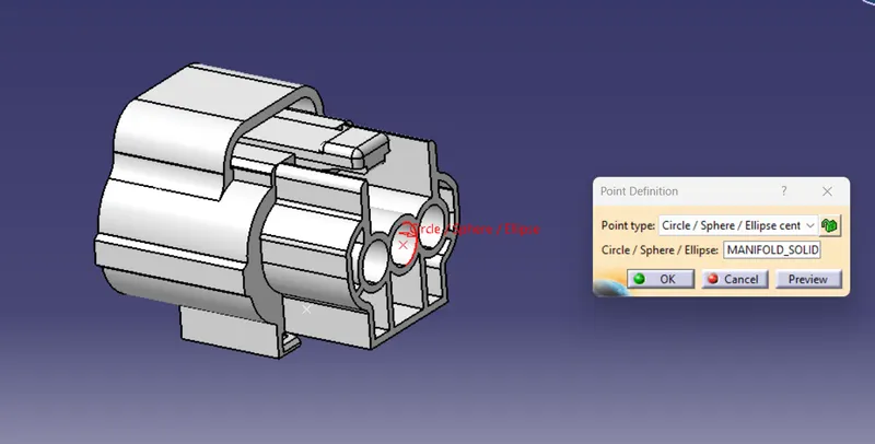
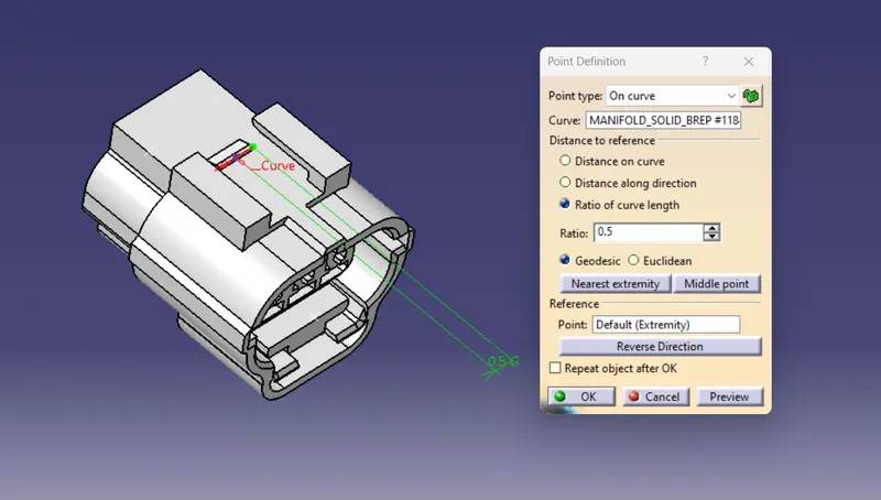
Given Axis System connector connection side.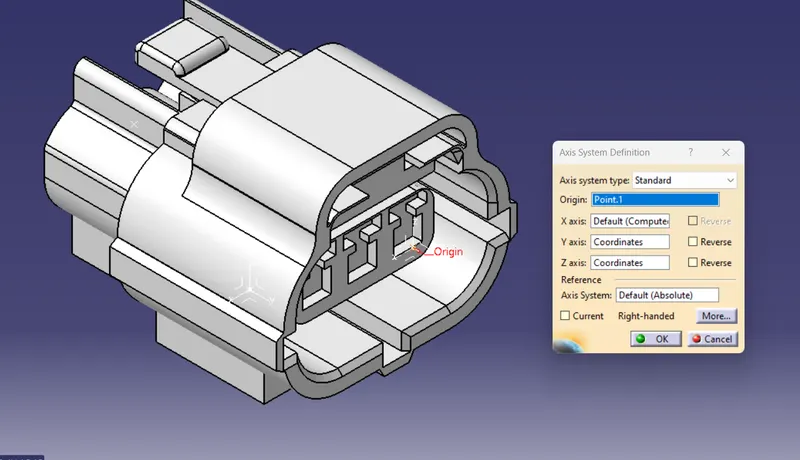
Part Changed to Electrical part design Then model defines as a 3 teriminal connector.
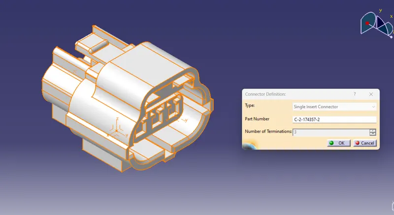
Then Bundle connection point is defined on the Bundle connector side.
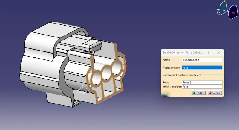
The connector connection side is defined as the connector connection point.
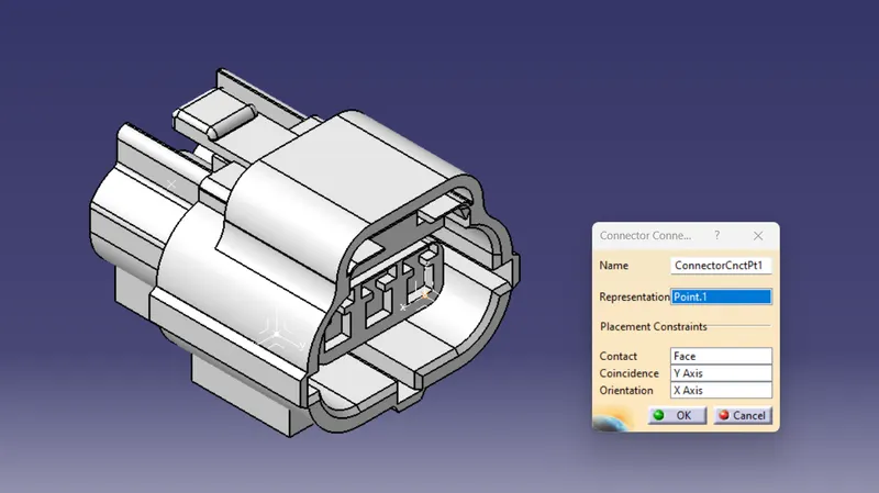
The cavity connection side is defined as a Cavity connection point.
Mounting Clip:
First, I downloaded the model from the given link.
Tyco 85229-1 – (https://www.te.com/usa-en/product-85229-1.html?q=85229&source=header)
Open Mechanical Design -> Part Design in part design given a Center point with help of Between point.
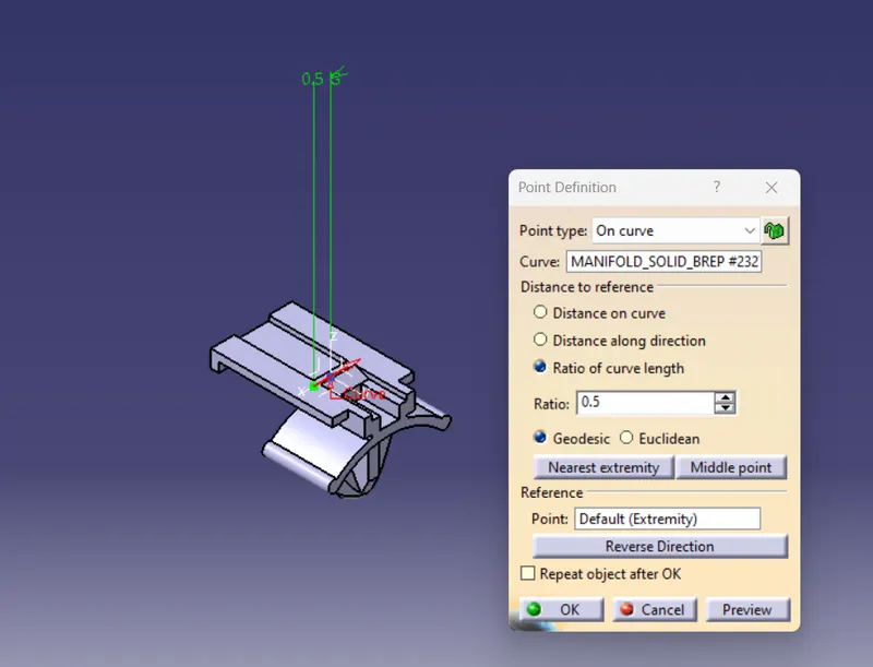
Given the Axis System Mounting side.
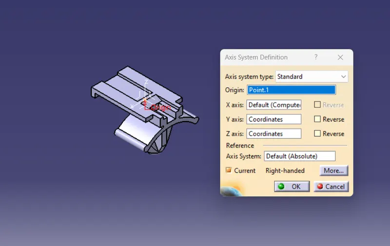
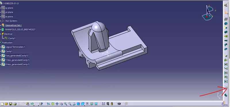
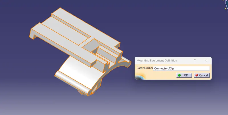
Part Changed to Electrical part design Then model defines as an Equipment.
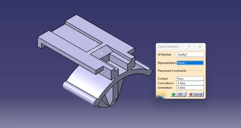
The mounting Side is defined as cavity definition.
Elctric Assembly Design:
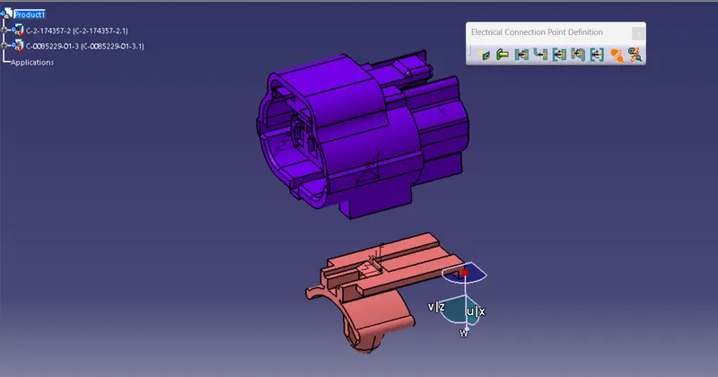
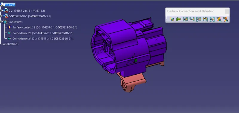
Now create an electrical assembly design product file import the connector 1 and mounting clip part drawings.
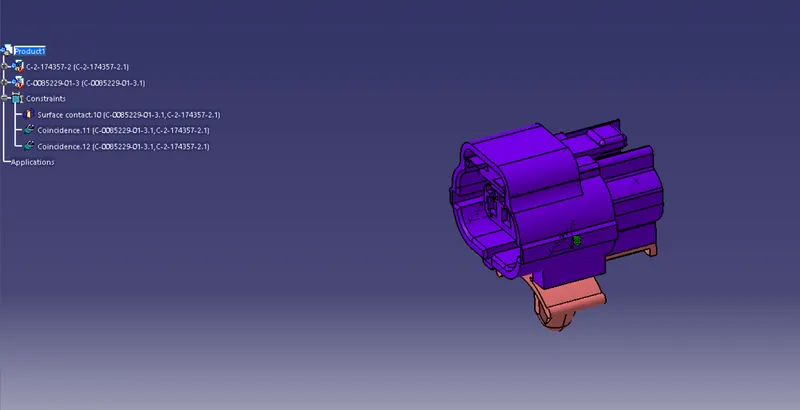
Now click on connect electrical devices command and select the First connector & next Mounting(cavity) clip parts. The parts are connected specified direction.
Catalogue creation:
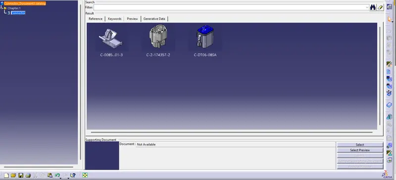
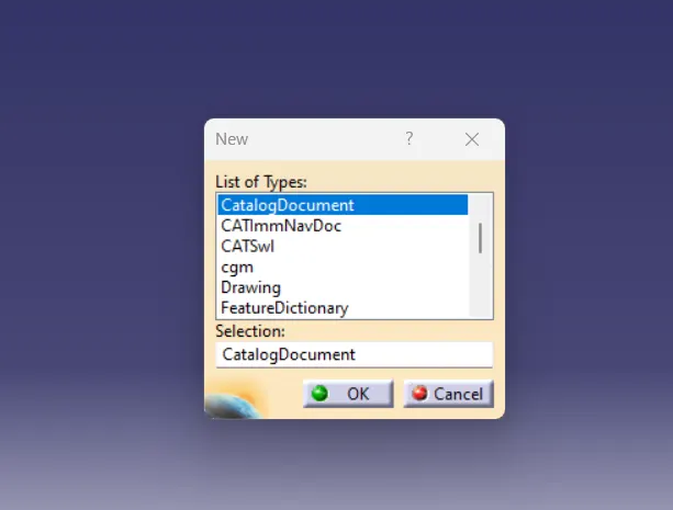
Click on File New In List of Types : Catalog Document , a small window like below pops . up where the highlighted blue coloured selection ( Catalog Document ) has to be selected .
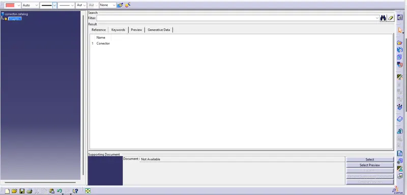
A new window opens up as shown below
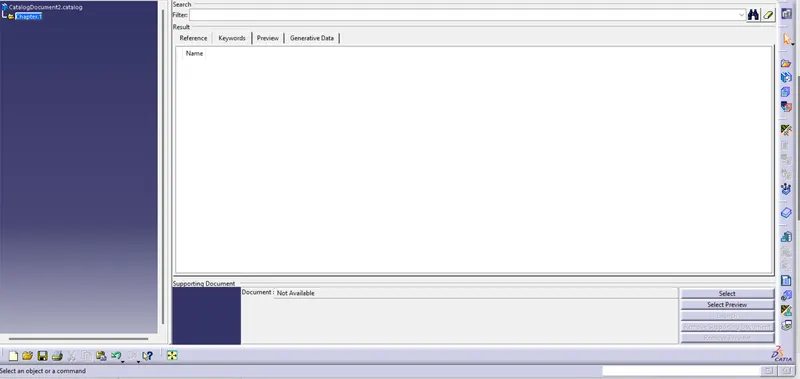
3. Towards right of the window you can find highlighted tab ( chapter ) .
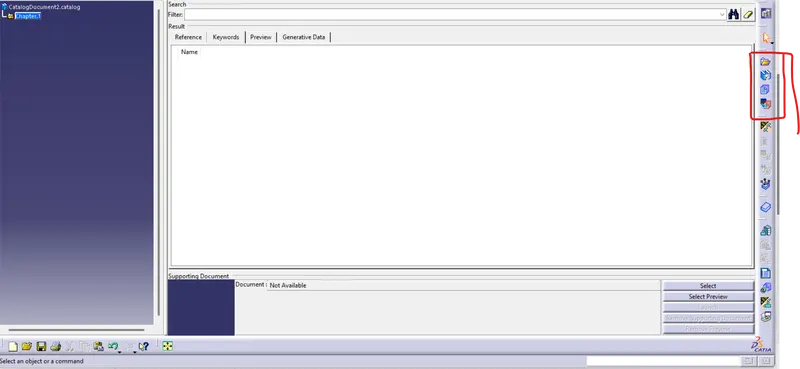
As shown in above tab select the Icon - add family .
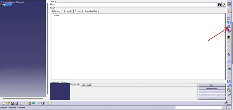
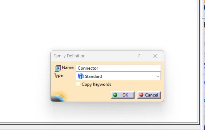
Clicking on the above Icon > a small Family . Definition window opens up .
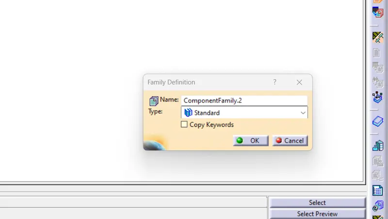
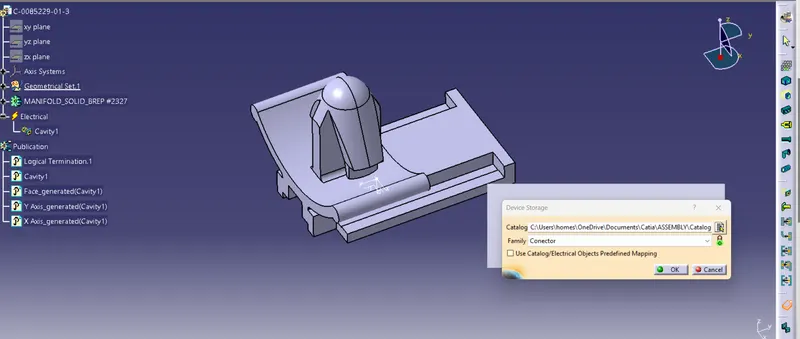
So in this we are considering the creating a ConnectorCatalog creation so in At last , Click on OK .