Wiring harness design in CATIA V5 - 3D modeling Week 2 Challenge
Week 2-: Wiring harness design 3D modeling Challenge
1. Introduction-: In this challenge we will be defining the bundle connection point, connector connection point, cavity connection point in connector 3d model & defining the connector as an electrical connector in Electrical part design workbench. Define all the properties & design the components keeping all the design intents and mating intents in considerations.
2. Definitions-:
a. Connectors-: A connector is a coupling device that joins electrical terminations to create an electrical circuit. Connectors enable contact between wires, cables, printed circuit boards, and electronic components.
b. Mounting Clips-: Mounting Clips are used for supporting & mounting the connectors on the brackets, channels, panels or surfaces. The clips varies as per the mounting requirements and connector cavity.
c. Bundle Connection Points-: The Bundle Connection points are the representation of connection of multiple wires into the terminal joints. It is the representation of the wire joints in bundle at the terminals junction in the connector.
d. Connector Connection Points-: Connector Connection points are the representation of the mating points of two joining connectors(i.e. male & female connectors mating point). The points define the orientation and the mating axis of the two connectors when they are joint together.
e. Cavity Connection Points-: The Cavity Connection points are the representation of the mating of mounting clips & connector cavity. These points define the orientation and the mating point for the mounting clips and the connectors.
3. Modelling & Defining of Electrical connectors in Catia V5-:
a. Connector 1 (Deutsch DT06-08SA, Male) -:
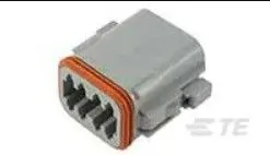
Objective-: We need to download the CAD data of the connector & define the bunde connection point, connector connection point & axis system. Define the connector as an electrical connector using Electrical part workbench.
Procedure-:
- Download .igs file format CAD data from the external source.
- Modelling of the part model in the part workbench and defining the bundle coonnection point, connector connection point by taking the references from the 3D Cad model.
Bundle Connection Point-:
1. Select the reference for the point from the terminal connection side of the connector.
2. Define the middle point in the Part workbench on the reference taken.
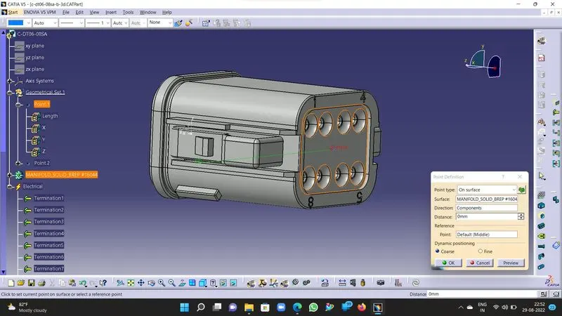
Connector Connection Point & Axis-:
1. Select the reference for the point from the Connector mating face or surface.
2. Define the middle point using Part workbench on the reference taken.
3. Once the point is defined, create an axis system using the point as the origin and define the orientation for the axis system such that the Y axis should face the mating direction, X axis should face the locking direction of the connectors & Z axis should be normal to the mating direction of the connectors.
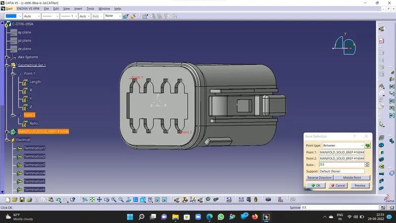
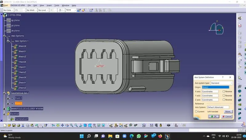
Defining of Electrical Connector, Bundle Conection point & Connector connection point in Electrical Part Workbench-:
1. Save the connector as .CATpart in the part workbench & switch to electrical part workbench for same part file.
2. Now define the Connector as an electrical connector using the "Define Connector" tool in Electrical workbench.
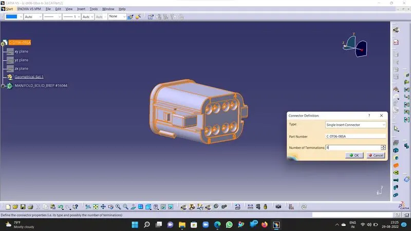
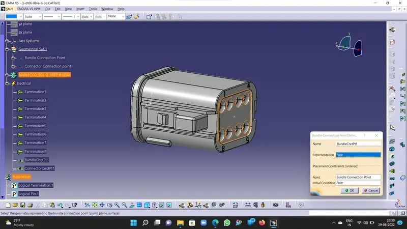
3.Now define the bundle connection point using Define bundle connection point tool as illustrated below. Its properties will be stored in the part body.
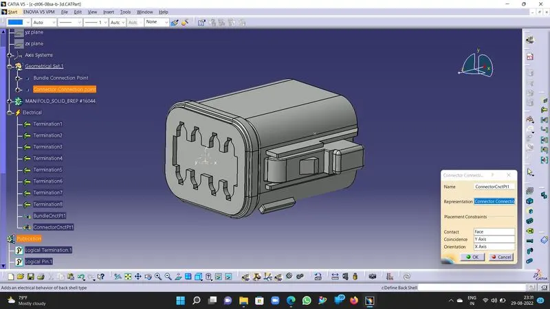
4. Now define the connector connection point using the Define connector connection point tool as illustrated below.
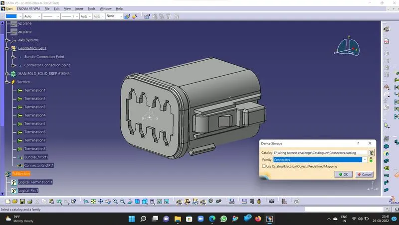
5. Now the Connector is defined as an electrical connector & we can store the electrical connector in the pre-defined/ stored catalogue for fututre reference as illustrated below.
6. Save the part body with the part number or the connector number as the .Catpart in the desired location.
b. Connector 2 (Tyco 174357-2, Female) -:
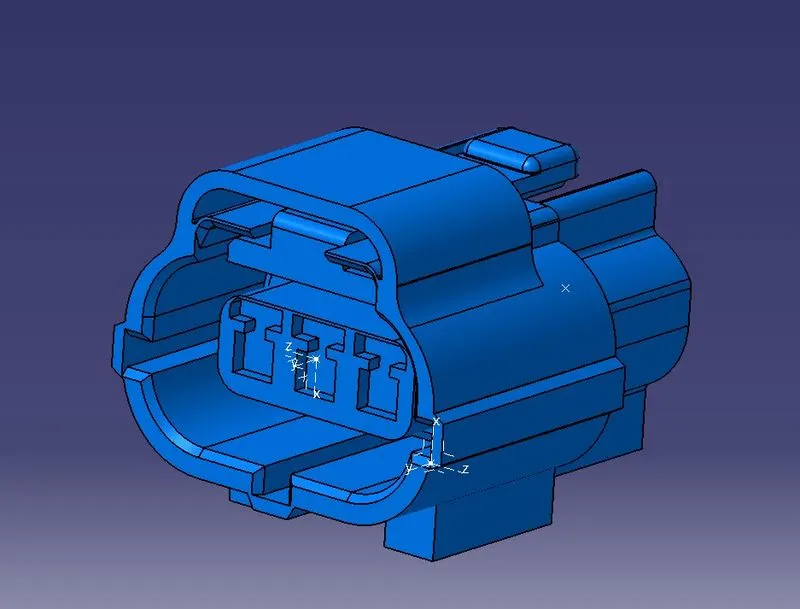
Objective-: We need to download the CAD data of the connector & define the bunde connection point, connector connection point, Cavity connection point & axis system for connector, cavity points. Define the connector as an electrical connector using Electrical part workbench.
Procedure-:
- Download .igs file format CAD data from the external source.
- Modelling of the part model in the part workbench and defining the bundle coonnection point, connector connection point, cavity connection point by taking the references from the 3D Cad model.
Bundle Connection Point-:
1. Select the reference for the point from the terminal connection side of the connector.
2. Define the middle point in the Part workbench on the reference taken.
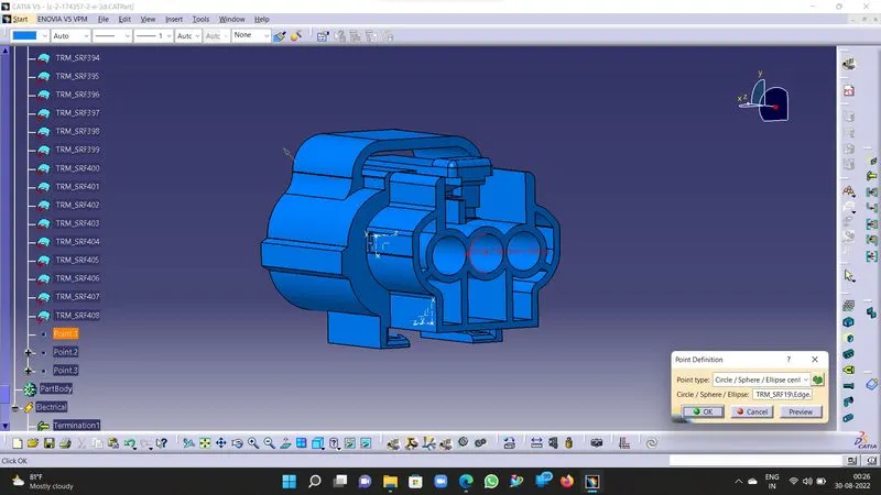
Connector Connection Point & Axis-:
1. Select the reference for the point from the Connector mating face or surface.
2. Define the middle point using Part workbench on the reference taken.
3. Once the point is defined, create an axis system using the point as the origin and define the orientation for the axis system such that the Y axis should face the mating direction, X axis should face the locking direction of the connectors & Z axis should be normal to the mating direction of the connectors.
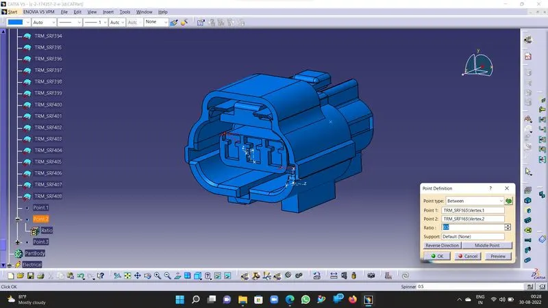
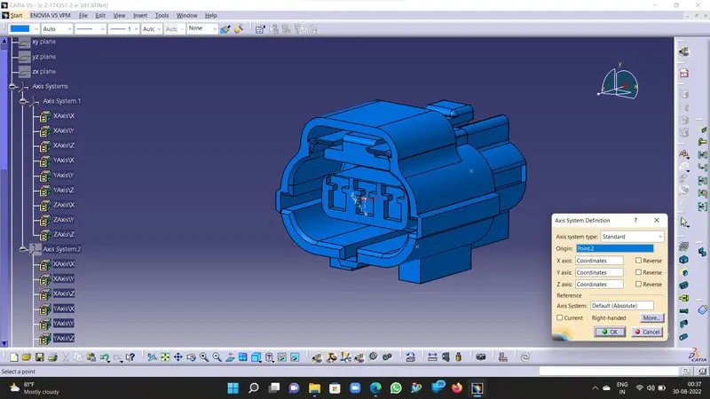
Cavity Connection Point & Axis-:
1. Select the reference for the point from the Cavity mating face or surface.
2. Define the middle point using Part workbench on the reference taken.
3. Once the point is defined, create an axis system using the point as the origin and define the orientation for the axis system such that the Y axis should face the mating direction, X axis should face the locking direction of the connectors & Z axis should be normal to the mating direction of the connectors.
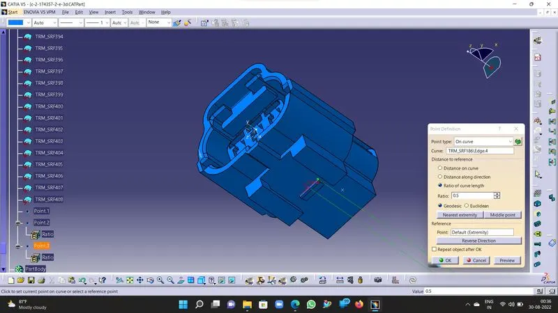
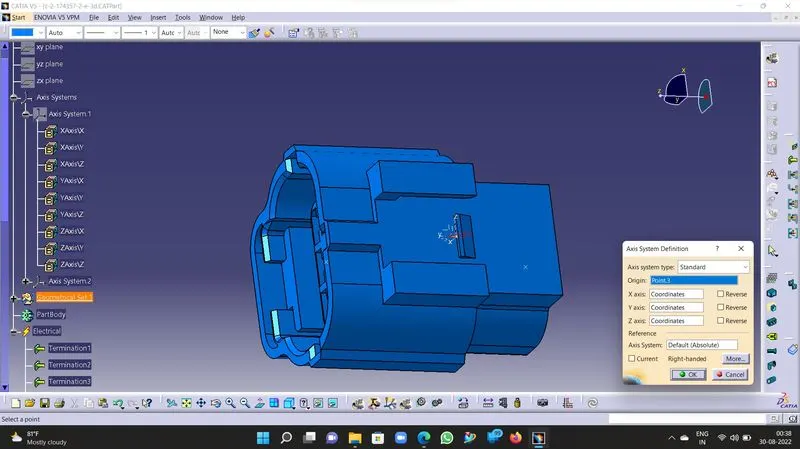
Defining of Electrical Connector, Bundle Conection point, Connector & Cavity connection point in Electrical Part Workbench-:
1. Save the connector as .CATpart in the part workbench & switch to electrical part workbench for same part file.
2. Now define the Connector as an electrical connector using the "Define Connector" tool in Electrical workbench.
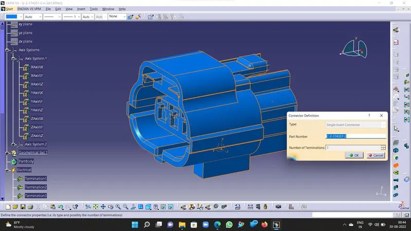
3.Now define the bundle connection point using Define bundle connection point tool as illustrated below. Its properties will be stored in the part body.
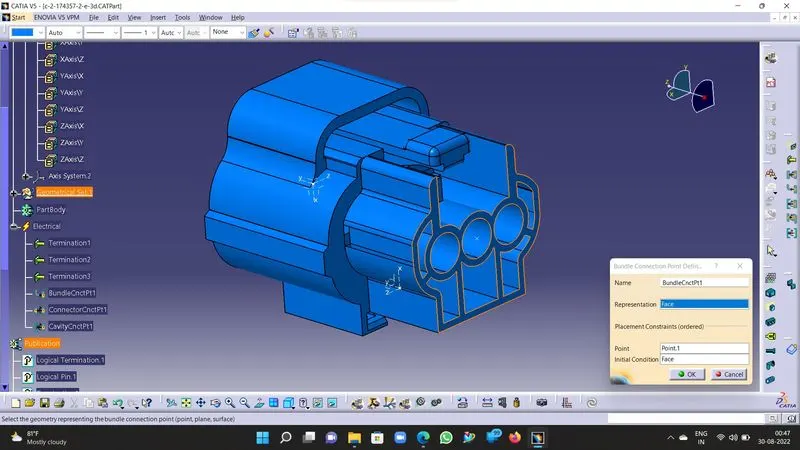
4.Now define the connector connection point using Define connector connection point tool as illustrated below. Its properties will be stored in the part body.
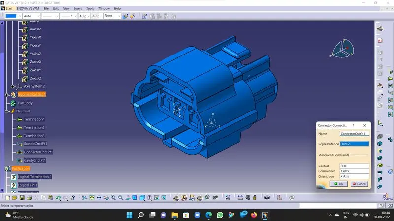
5.Now define the cavity connection point using Define cavity connection point tool as illustrated below. Its properties will be stored in the part body.
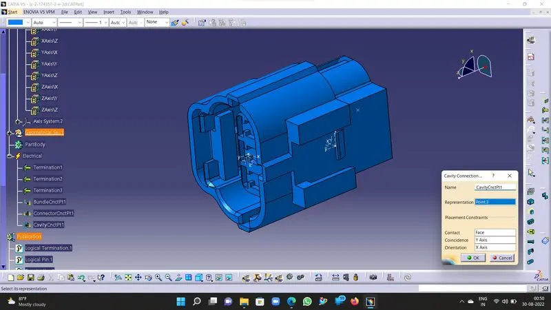
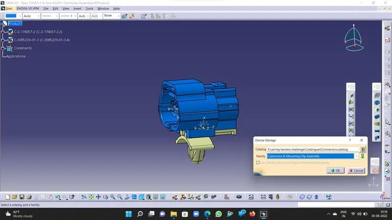
6. Now the Connector is defined as an electrical connector & we can store the electrical connector in the pre-defined/ stored catalogue for fututre reference as illustrated below.
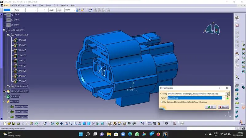
7. Save the part body with the part number or the connector number as the .Catpart in the desired location.
c. Connector 2- Mounting Clip (Tyco 85229-1) -:
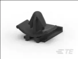
Objective-: We need to download the CAD data of the connector & define the Cavity connection point & axis system for clip. Define the mounting clip as a cavity using Electrical part workbench.
Procedure-:
- Download .igs file format CAD data from the external source.
- Modelling of the part model in the part workbench and defining the cavity connection point by taking the references from the 3D Cad model.
Cavity Connection Point & Axis-:
1. Select the reference for the point from the Cavity mating face or surface.
2. Define the middle point using Part workbench on the reference taken.
3. Once the point is defined, create an axis system using the point as the origin and define the orientation for the axis system such that the Y axis should face the mating direction, X axis should face the locking direction of the connectors & Z axis should be normal to the mating direction of the connectors.
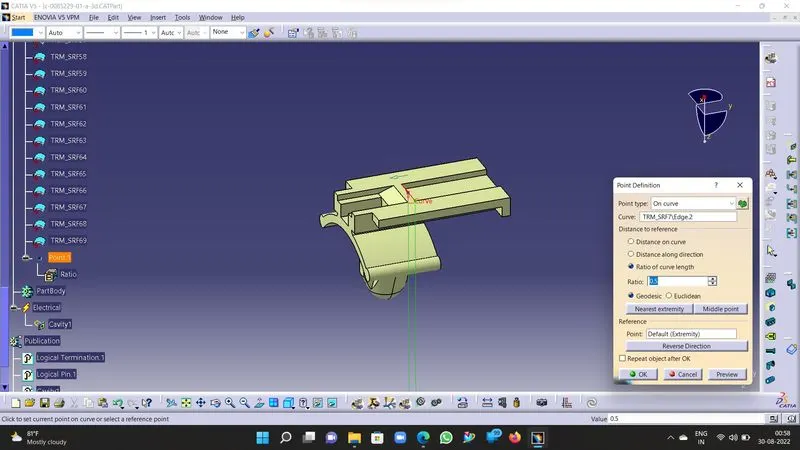
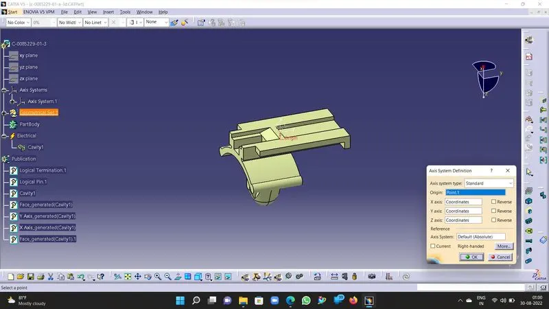
Defining of Mounting Clip cavity connection point as Cavity in Electrical Part Workbench-:
1. Save the connector as .CATpart in the part workbench & switch to electrical part workbench for same part file.
2. Now define the mounting clip as "Cavity" using the "Define Cavity" tool in Electrical workbench.
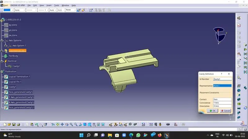
3.Now the Mounting Clip is defined as Cavity & we can store the clip in the pre-defined/ stored catalogue for fututre reference as illustrated below.
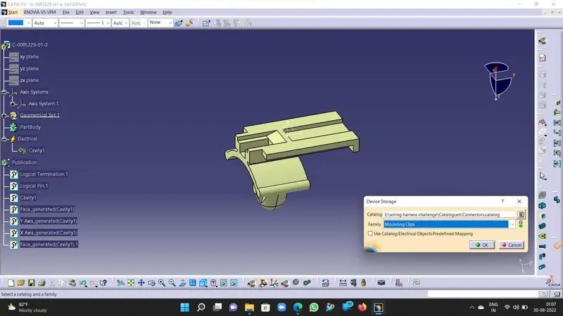
4. Save the part body with the part number or the connector number as the .Catpart in the desired location.
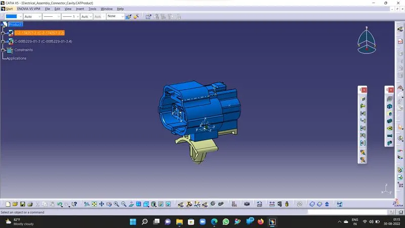
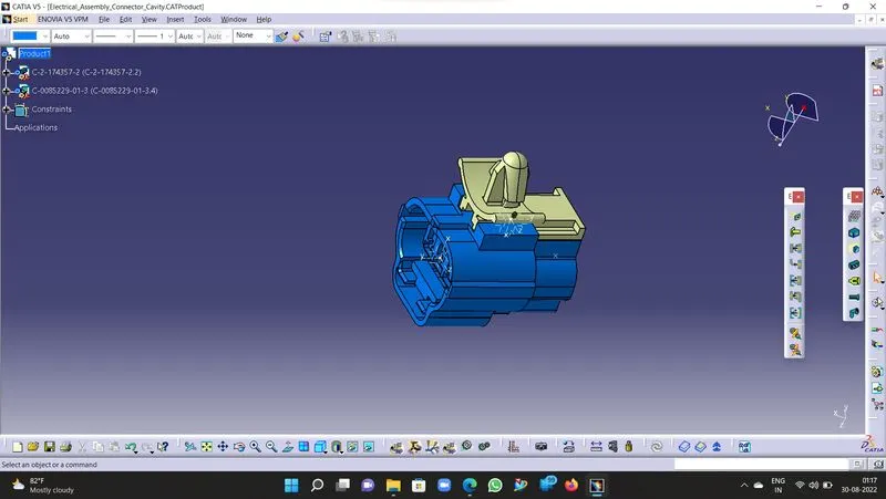
d. Electrical Assembly for Connector2 & Mounting Clip-:
Procedure-:
1. Switch to Electrical Assembly Workbench.
2. Copy the Part models from respective part model files & paste into product section in assembly workbench.
3. Adjust the orientation of the part models in the mating direction.
4. Now using the Connect Electrical Devices tool connect the connector & mounting clip in the defined orientation.
5. Now the parts are assembled in the mating axis as defined, save the assembly & store it in catalogue for your future reference with the part number & reference number.