Week 9- Unsteady moving zones Approach
AIM:
To simulate the turbomachinery component using the Moving Mesh method in the transient state to understand the flow physics.
THEORY:
MOVING MESH APPROACH:
Moving mesh approach is used only for the unsteady phenomenon like,
- Vortex-induced flow.
- Interaction of vortex with bodies.
In Moving Mesh Approach,
- Mesh is moving.
- Topology of mesh changes with time.
- Control volume changes as mesh changes.
- It is an unsteady phenomenon.
PROCEDURE TO SET UP THA CASE FOR MOVING MESH METHOD:
GEOMETRY:
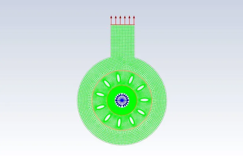
- First, import the mesh into fluent.
- Using the display option the mesh can be visualized.
TURBULENCE MODEL AND MATERIALS:
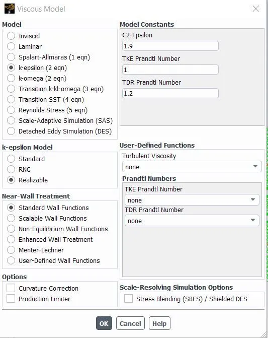
- In the viscous model k-epsilon, a realizable model is used.
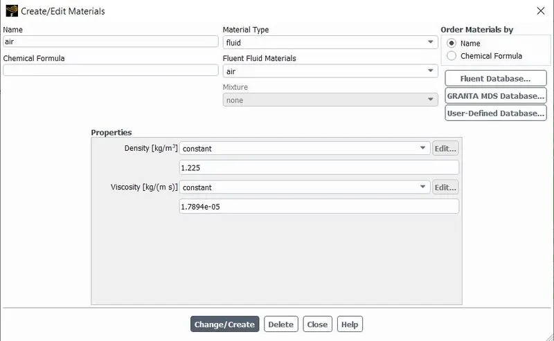
- In materials for fluid air is used with constant parameters.
CELL ZONE CONDITION:
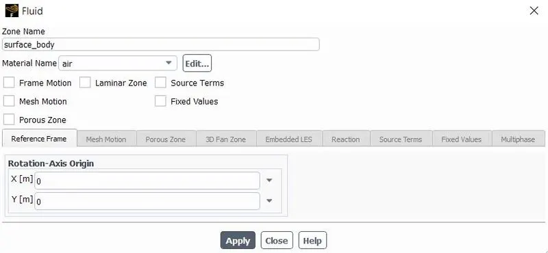
- In a cell, zone condition is used to define that the surface of the mesh is rotating or stationary.
- Here in this problem, we have three cell zone conditions and all the three-zone should be set at fluid type.
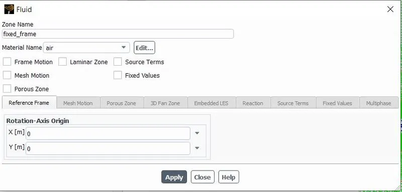
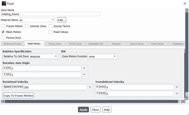
- In a rotating frame, the mesh motion option is used to rotate the mesh.
- The rotational velocity is 300rpm.
BOUNDARY CONDITIONS AND MESH INTERFACES:
- In boundary conditions inlet is set as a pressure inlet and the outlet is set as a pressure outlet.
- Check that all the boundary condition is set correctly.
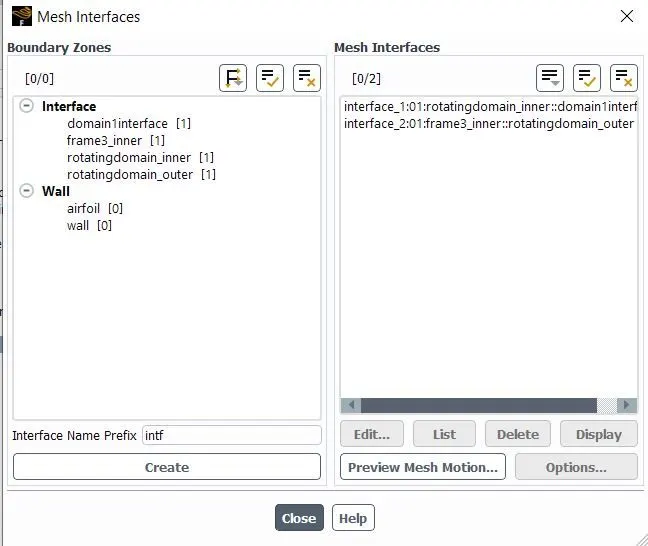
- A Mesh interface is used to set the interface between two surfaces to flow the fluid.
SOLUTION METHODS AND RUN CALCULATIONS:
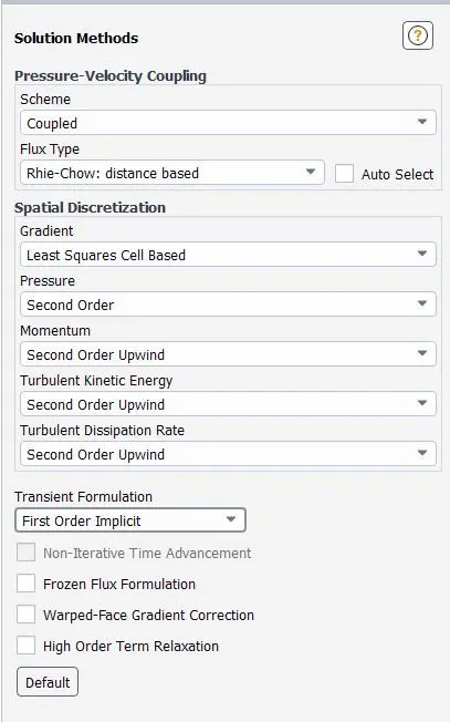
- In solution method, coupled solver with second-order up-wind is used.
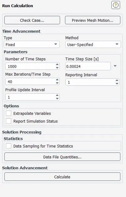
- In run calculation, since the simulation is transient based the time step size(s) is 0.00024 s.
- The number of time steps is 1000 and the maximum number of iteration per time step is 40.
RESULTS:
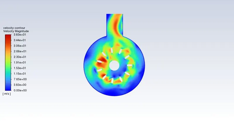
Velocity Contour:
Vorticity Contour:

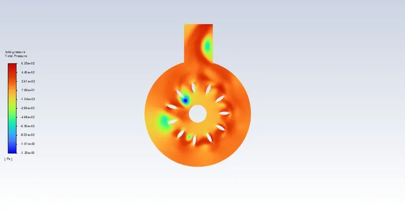
Total Pressure Contour:
Animation video for Velocity contour:
CONCLUSION:
From this simulation, we came to know how to set the mesh motion method and mesh interface.