Week 9 Tension and Torsion test challenge
AIM:
To perform the tension and torsion test on the specimen.
OBJECTIVE:
To perform the tension and torsion test on the specimen provided below the video corresponding to the challenge.
For the tension test, displace one end of the specimen to 18mm while keeping the other fixed. You will need to find out the total deformation, equivalent stress and temperature of the specimen and attach appropriate images to show your results.
For the torsion test, you will need to displace one end of the specimen to an angle of 1200 degree. Find out the total deformation, equivalent stress and temperature of the specimen and attach images to show your results.
PROCEDURE: For tension Test
. Select Explicit Dynamics, drag and drop into Project Schematic.
. Steel 1006 is chosen under Engineering Data.
. Under geometry tab, import the given geometry, double-click to open Space Claim to register the model.
. Set a cartesian co-ordinate system, one on each end of the given model.
. Mesh size was set to 1.5mm.
. The mesh method was set to tetrahedrons.
. A face sizing was given on each end of the model, with sphere of influence with the respective co-ordinate systems. Sphere radius was 22mm and Element size set to 1mm.
. Under explicit dynamics tab, we set the analysis to 1 step with end time 1e-3s.
. Displacement of 18mm is given to one side of the model along the axis of the model.
. The other end of the model is fixed.
. Equivalent Strain, total deformation, temperature (user defined from Solutionsà worksheet) and Equivalent Stress plots are requested from the solver as outputs.
. Run the simulation by clicking on SOLVE.
PROCEDURE: FOR torsion Test
. Select Explicit Dynamics, drag and drop into Project Schematic.
. Steel 1006 is chosen under Engineering Data.
. Under geometry tab, import the given geometry, double-click to open Space Claim to register the model.
. Set a cartesian co-ordinate system, one on each end of the given model.
. Set a cylindrical co-ordinate system, at the center of the model. Ensure the rotation is about axis of the model.
. Mesh size was set to 1.5mm.
. The mesh method was set to tetrahedrons.
. A face sizing was given on each end of the model, with sphere of influence with the respective co-ordinate systems. Sphere radius was 22mm and Element size set to 2mm.
. Face sizing is also given to the 3 faces in the middle.(2 faces with 1mm mesh and middle face with 0.5mm mesh)
. Under explicit dynamics tab, we set the analysis to 1 step with end time 1e-3s.
. Displacement of 1200deg is given to the one side of the model along the axis of the model, twisting the model.
. The other end of the model is fixed.
. Equivalent Strain, total deformation, temperature (user defined from Solutions worksheet) and Equivalent Stress plots are requested from the solver as outputs.
. Run the simulation by clicking on SOLVE
These conditions are used in the simulation process
MATERIAL PROPERTIES
STEEL 1006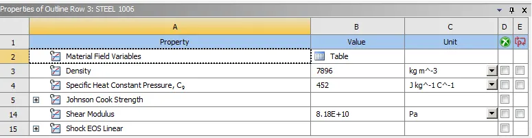
COORDINATE SYSTEM(FOR TENSION TEST)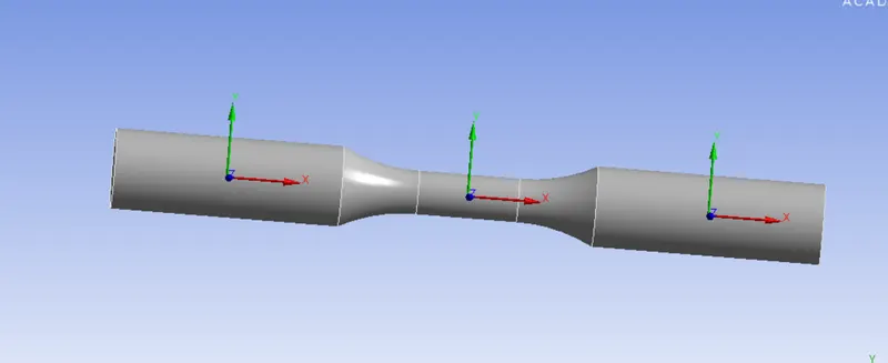
COORDINATE SYSTEM (FOR TORSION TEST)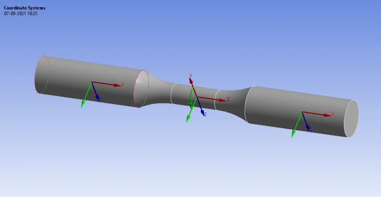
MESHING (FOR TENSION TEST)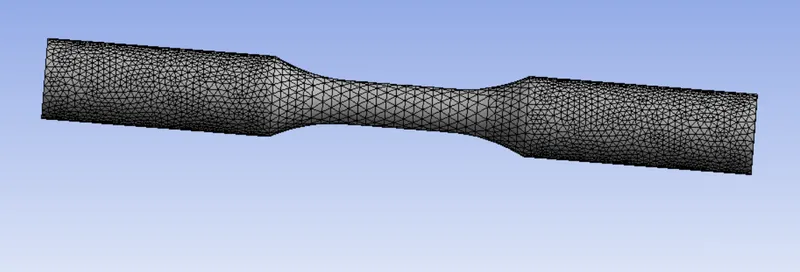
MESHING( FOR TORSION TEST)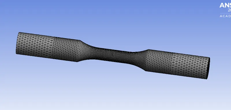
LOADS:
FIXED SUPPORT 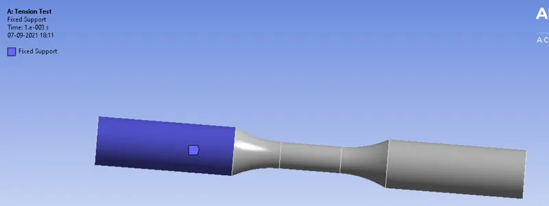
DISPLACEMENT(FOR TENSION TEST)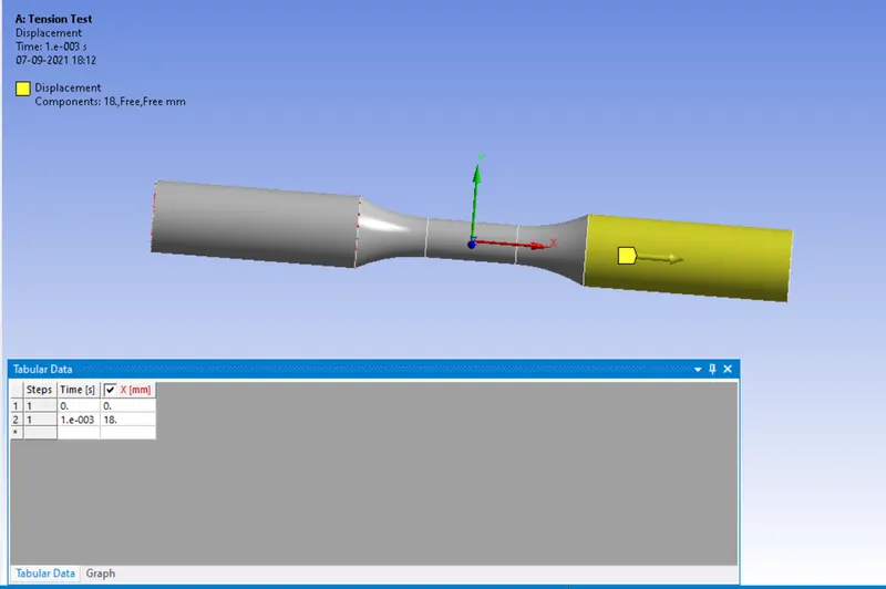
DISPLACEMENT FOR TORSION TEST 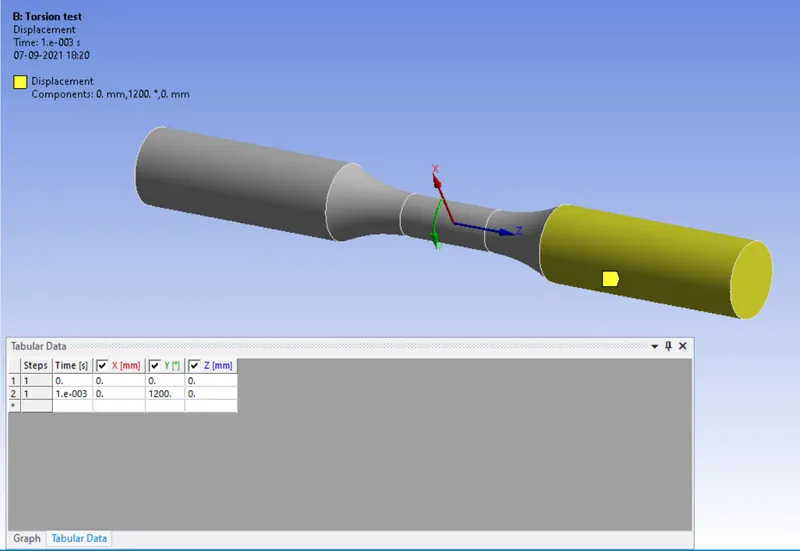
TENSION TEST RESULTS:
EQUIVALENT STRESS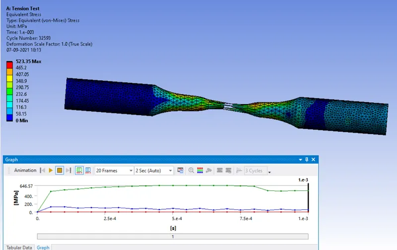
TOTAL DEFORMATION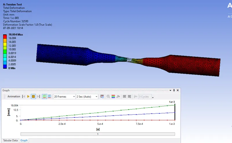
TEMPERATURE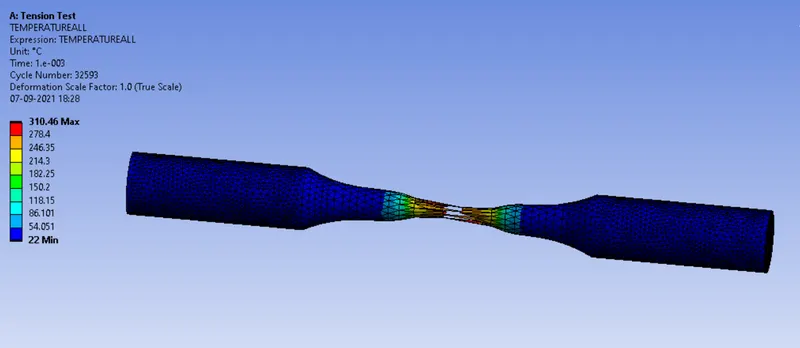
TORSION TEST:
EQUIVALENT STRESS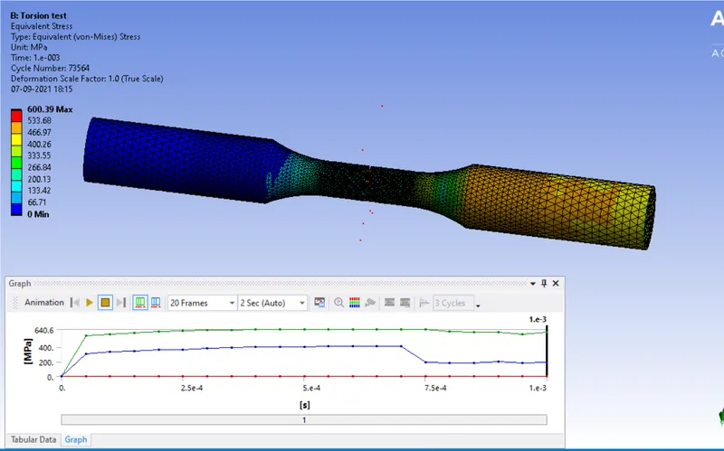
TOTAL DEFORMATION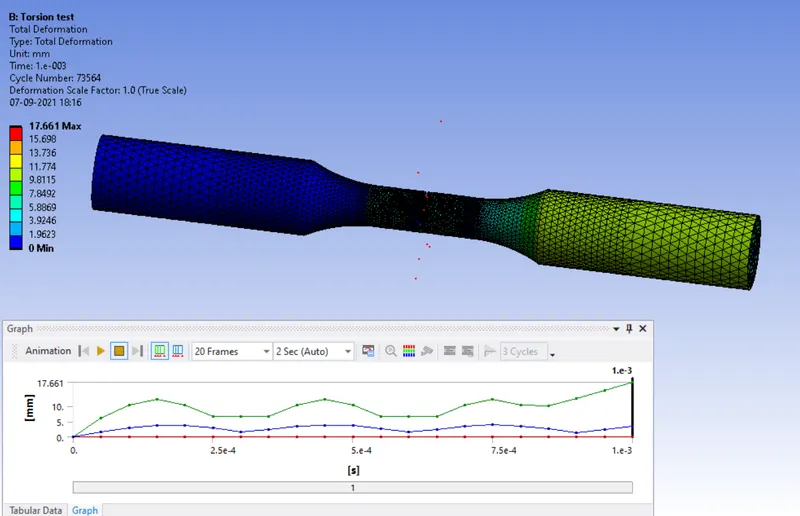
TEMPERATURE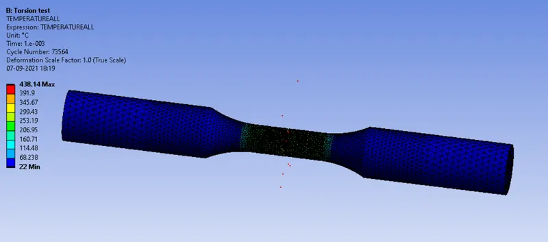
RESULTS COMPARISON
|
Test |
Eq. Stress (MPa) |
Tot. Deformation (mm) |
Temperature |
|
Tension Test |
523.35 |
18.004 |
310.46 |
|
Torsion Test |
600.39 |
17.661 |
438.14 |