Week 9 - Project - Master Section Development
To create a B pillar with master section we should follow the master section which they have in the B pillar creation.
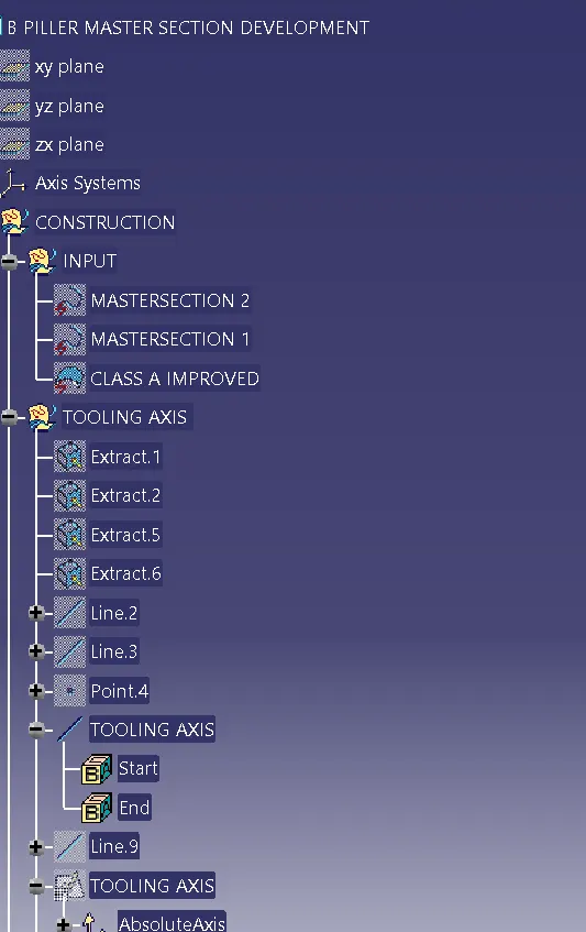
Firstly we have to create a tooling axis for the component of master section component and we have to check the draft ananlysis of the component.
creation of tooling axis is done by two methods, like from the bisecting method tooling axis and compass method.
Bisecting method is done by considering the adjucent lines from master section, we will get 4 lines from it.
After that we can create a point in between those 4 lines of the master section by point direction command.After creation of the point draw a line by using point to point command from it.
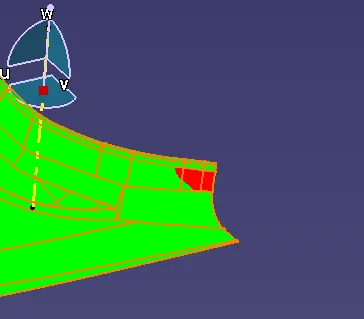
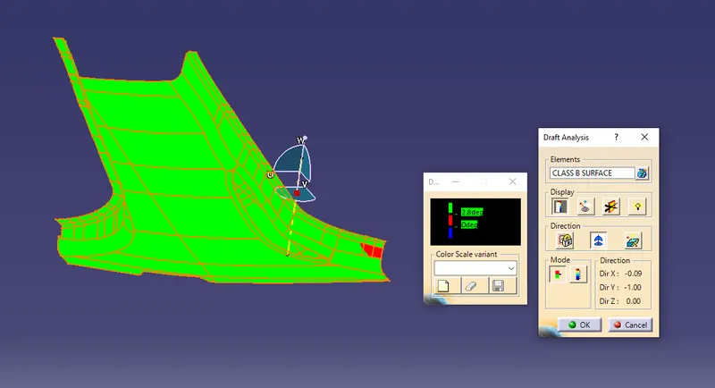
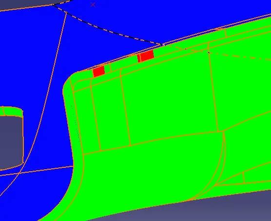
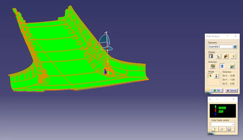
While by doing with a compass method same procedure is been followed but when we choose a plane command in that direction has been as compass direction and extracting some surfaces from the B pillar we will get line which can be considered as main tooling axis of the component.from this main tooling axis all the surfaces of the B pillar should follow the draft analysis of the component. The minimum draft angle 3 degree should follow draft direction of the component and which shows a green color of the component. If it's not just orienet the compass direction of draft direction.
after creation of tooling axis of the component we do conduct draft analysis for the master section which follows the draft angle of the component which follows 3 degree draft angle.
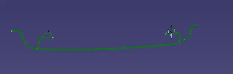
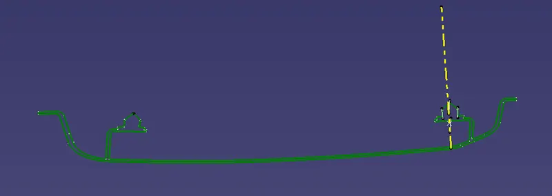
To create a tooling axis of the component we should take the lines which are adjacent to each other and make a point in between them, and create a tooling axis for the component.
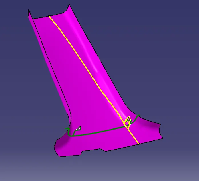
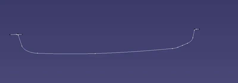
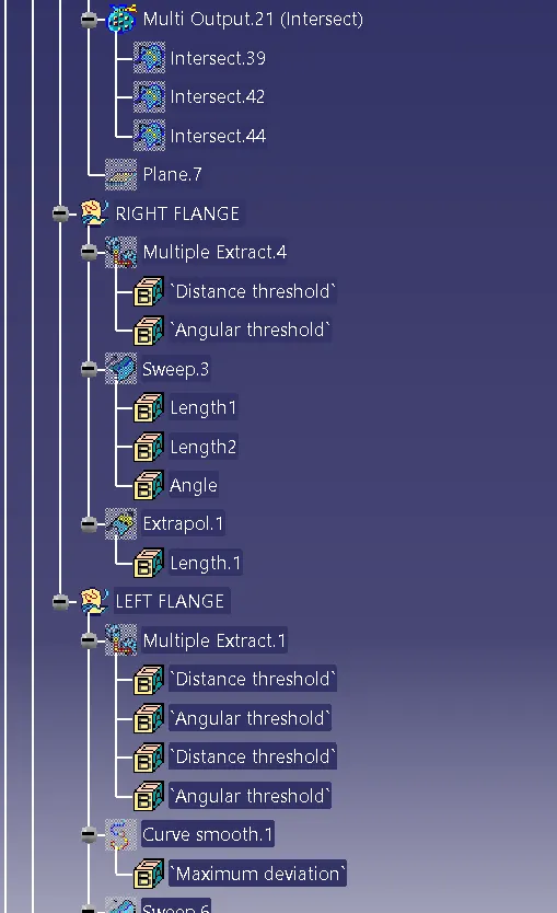
To create a flanges on both the sides for class A surface we shall extract the component and make a "offset" of the component with a offset angle of 2.5mm with a proper direction.
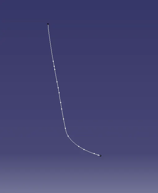
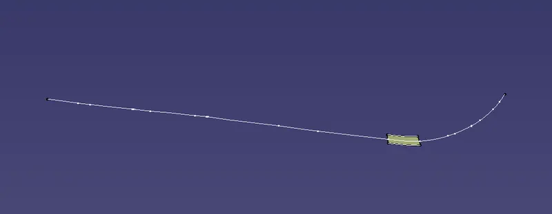
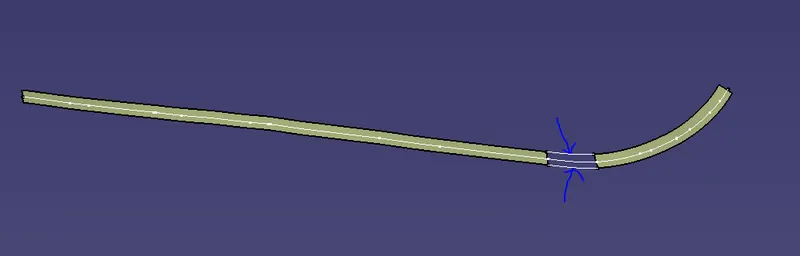
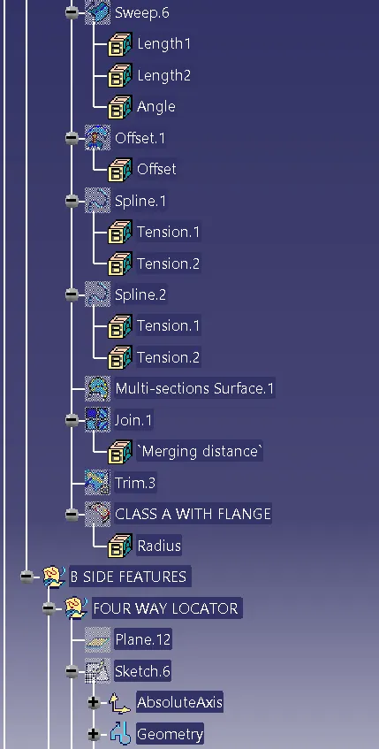
After offseting the flanges we will get gap in between the surfaces so to fill that gap need to extract the surfaces and Apply operation spline for that gap and multisection the surface and join it with a main surface.
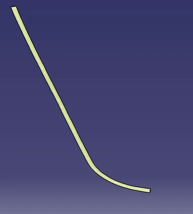
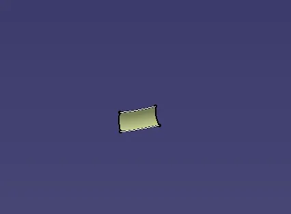
after creation of flange on right side we have to create a left flange by following the same procedure for creation of left flange by extracting the sides and making offset with a main substance and performing the operation like sweep, extrapolate and final trimming and all. offset the surface with a gap of 2.5mm with a proper direction.
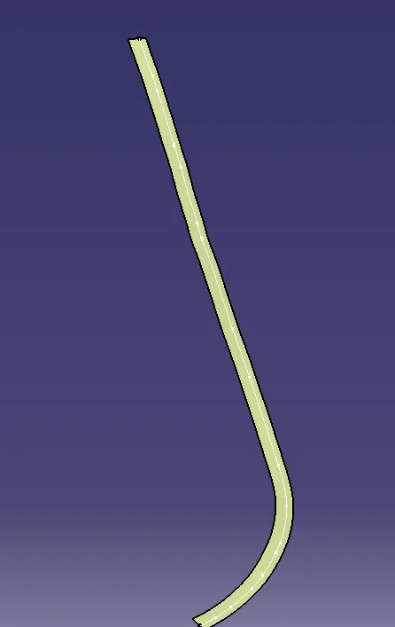
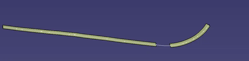
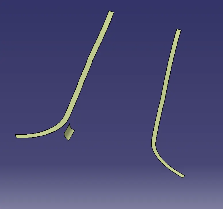
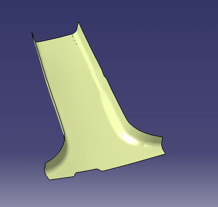
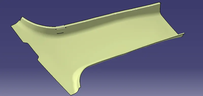
Doing all the opertions on both the sides we will finally get a good surface with flanges on both the sides like to say class A surface with the flanges and class B surface with flanges.
To create a flanges on both the sides follow the master section given in the B pillar part. Measure the distance 0f master section which gives as 2.5mm on the given part.
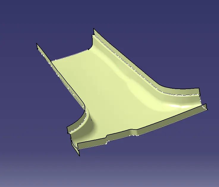
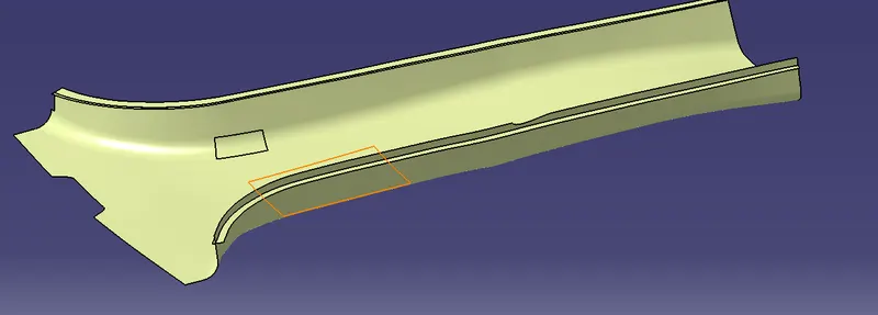
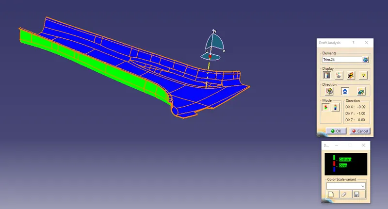
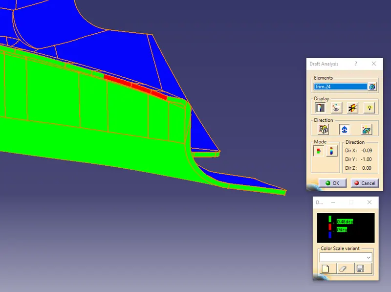
The creation of class b surface is made with the final trim of the component with flanges on both the sides. after creation of class b surface do conduct the draft analysis of the component which follows the draft angle of 3 degree draft angle.
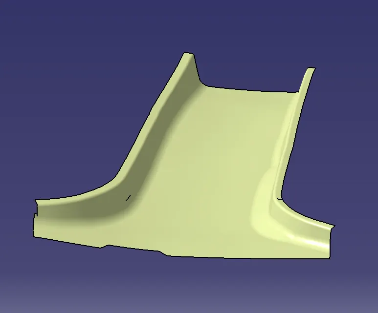
To create a C surface consider the outer surfaces of the component by multi extracting them with proper dimensions which is given below.
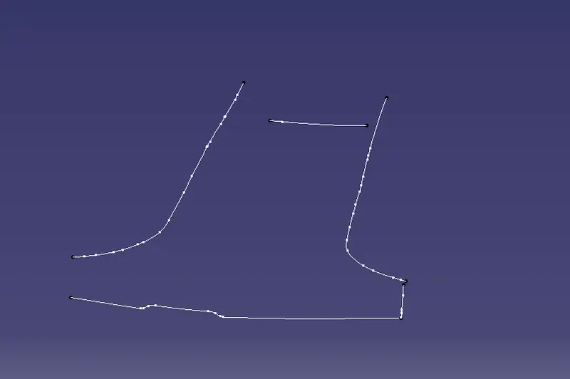
for the above picture we extracted the surfaces with a outer body of the component and we apply sweep for the above extracted surfaces with the main tooling direction axis with 87 degree for the component.
which follows the outer angle for the sweep direction if any gap araises just extrapolate the component and trim the extra surface and get a class c surface.
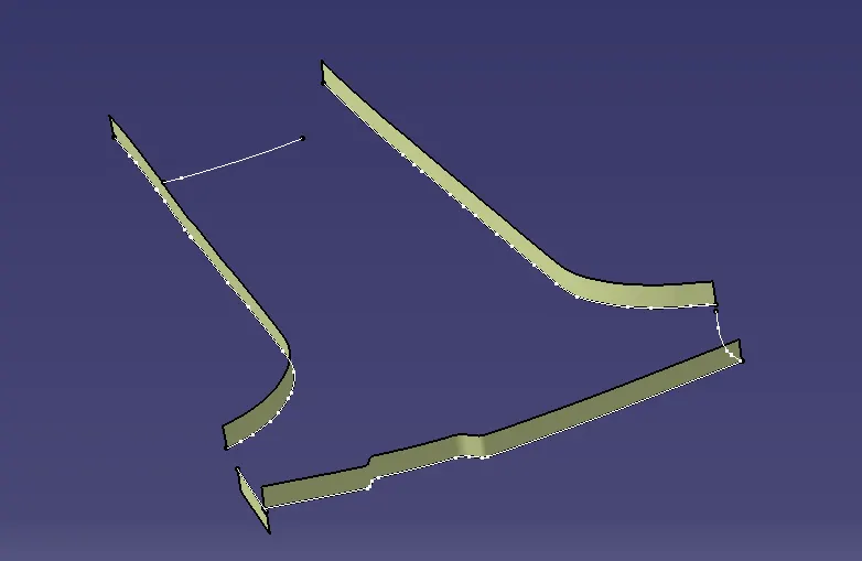
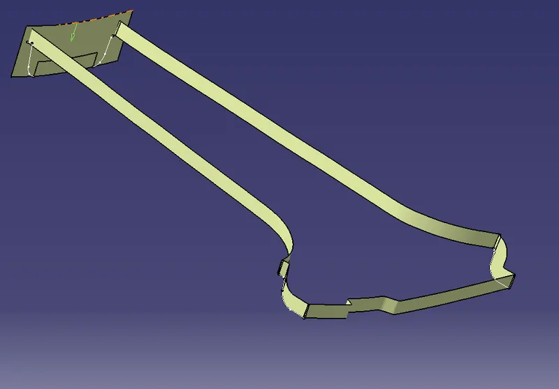
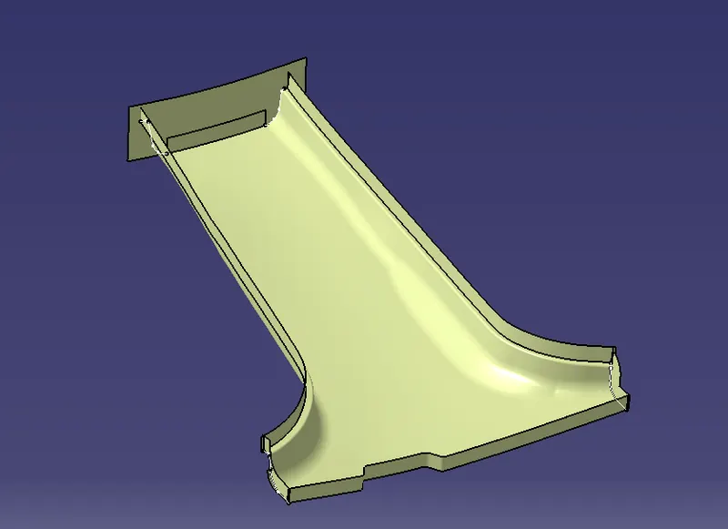
after creating a C surface component we should make it as a close surface which can be done by using the part design work bench with a thickness of 2.5mm for the component.
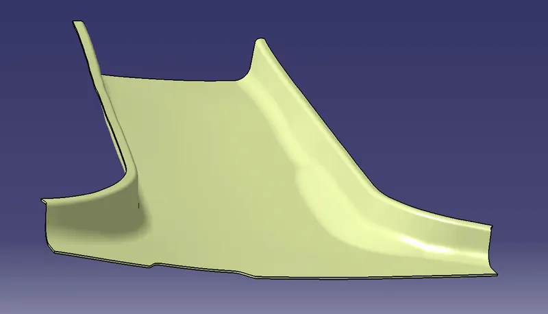
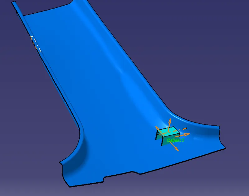
After creation of c surface creation we need to create a B side features which includes dog house, 4 way loactors and ribs on both the sides of the component.
1) Creation of Dog House
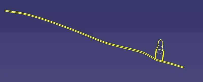
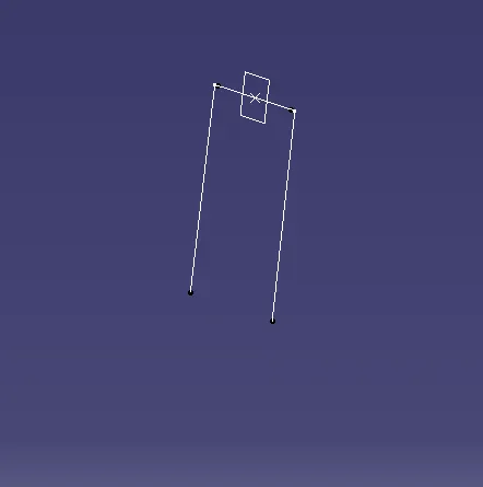
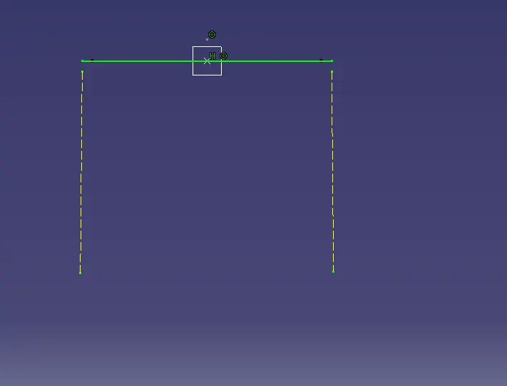
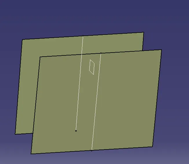
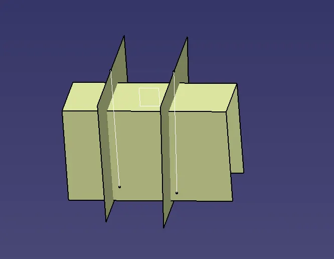
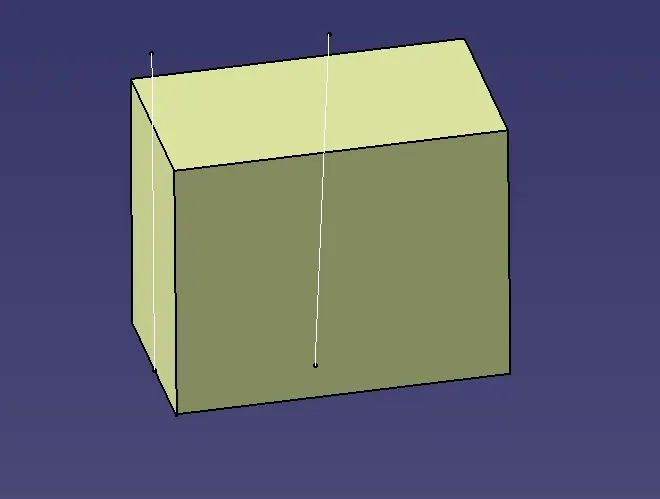
Firstly we have to extract the surfaces to create the dog house and extrude to them and make a final trim for to get a final dog house creation.
to create a cut section for the dog house just consider a line in which we have to extrude it upto some distance.
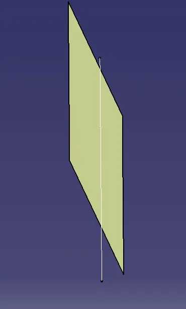
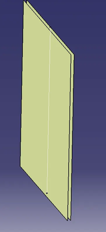
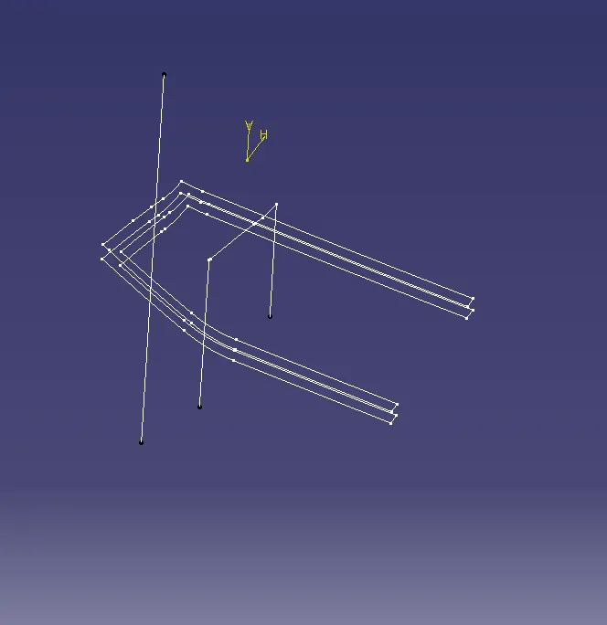
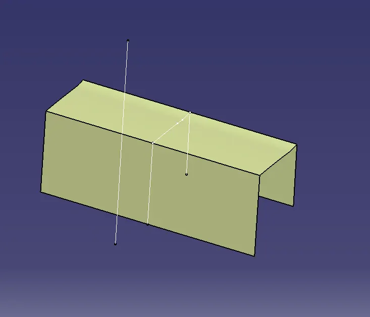
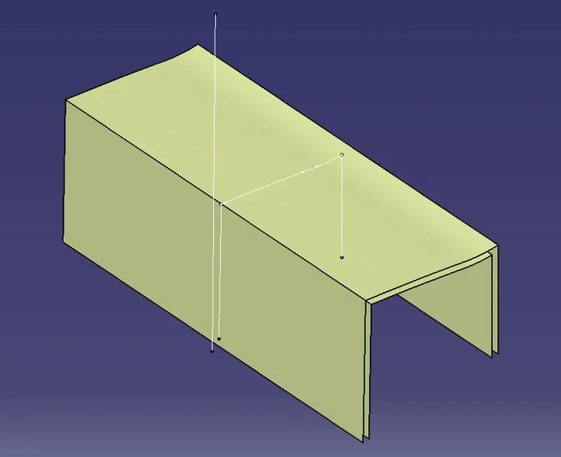
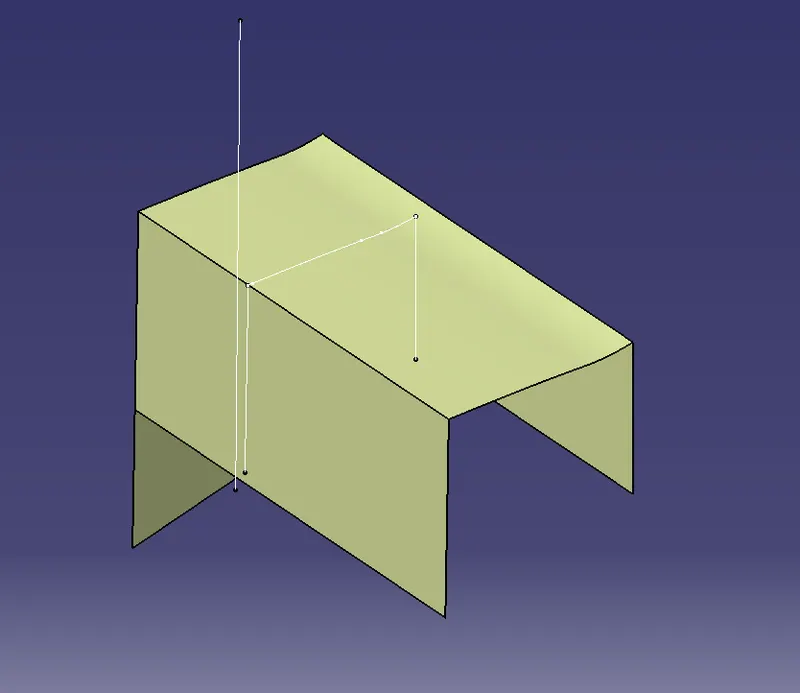
The dog house can be created according with the surfaces and following the design rules and make a final trim to get a proper shape of the component.
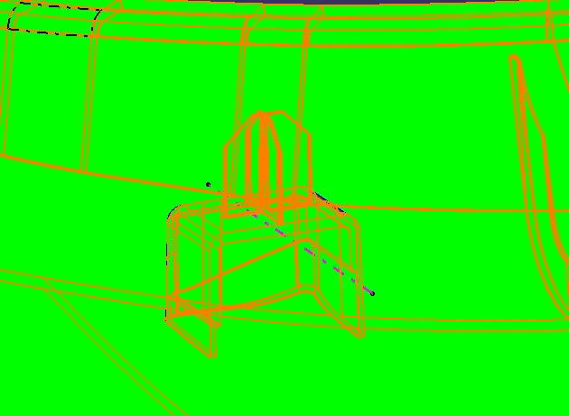
after creation of dog house do conduct the draft analysis for the dog house with a main tooling axis of the component which clears the draft angle of 0.5 degree with a main tooling axis of the component.
4 way locators can be created on a dog house by considering lines on it and make it pad for distance and padding can be thick upto a distance.
To create a locator on a dog house we need a point which can be created by considering the option in it.
and a plane is needed to create a 4 way locator on a dog house.
we shall create two lines with horizontal and vertical directions with it and apply pad for those by making thick surface from it.
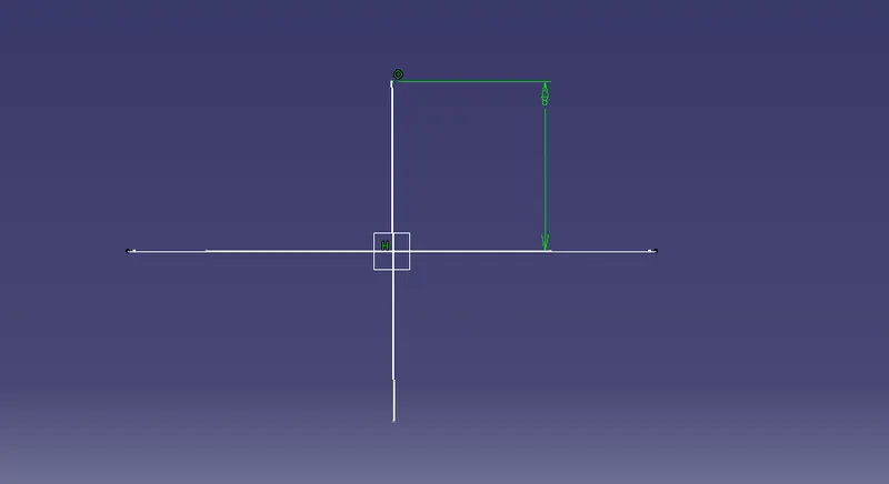
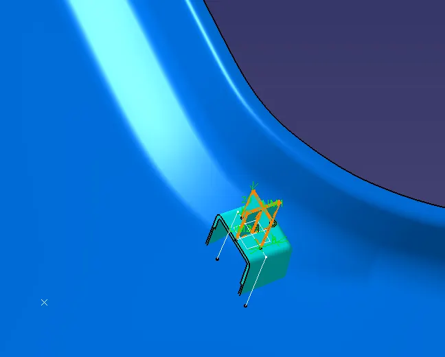
The dog house and 4 way locator can be shifted to another side of the component by using the translation method component upto some distances.
The ribs can be created on each side of the component with a minimum distance of 50 mm apart from each other.
To create a rib on B pillar component we need a line which can be made by considering a plane and a point on it.
after creating a line on B pillar just apply pad and make it thick and extract the surfaces and make it offset to a distance of 2 mm of the component.
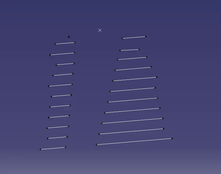
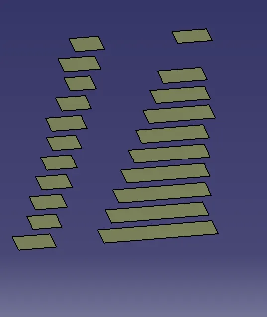
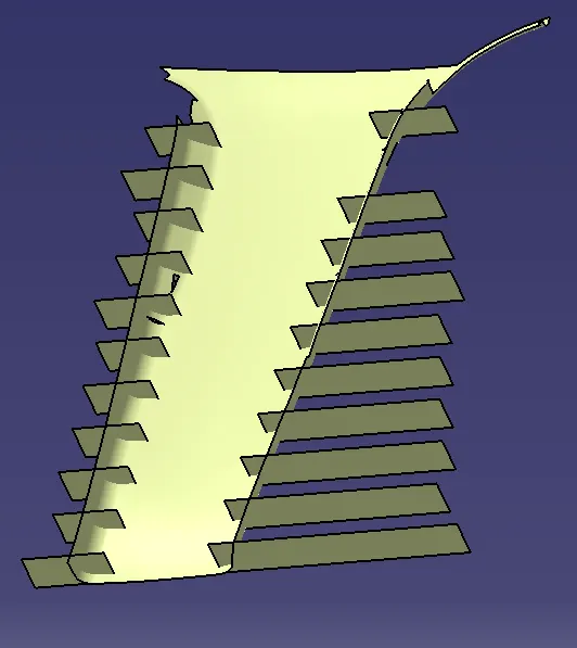
after creation of ribs on each side of the B pillar location after thickning it and trimming and all after getting a proper shapes of the component finally make a trim and get a shapes of the rib.
Do conduct the draft analysis for each of the component like to say for class A improved surface, class B surface and class C surface, dog house, 4 way locators and ribs on each sides of the component.
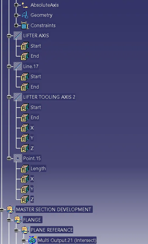
The side core or lifter axis can be created for draft analysis of the dog house inside portion which will not drafted with a main tooling axis of the component.
The side core tooling axis is going to create because draft angle for the inner side of the B side features can be drafted with this and which follows the design rules of the component.
We shall inform the class A team that where ever draft is not acceptable for the design considerations.
According to that only we need to create a side core or lifter axis of the component.
CLASS A SURFACE FOLLOWING THE DRAFT. WITHOUT FOLLOWING DRAFT.
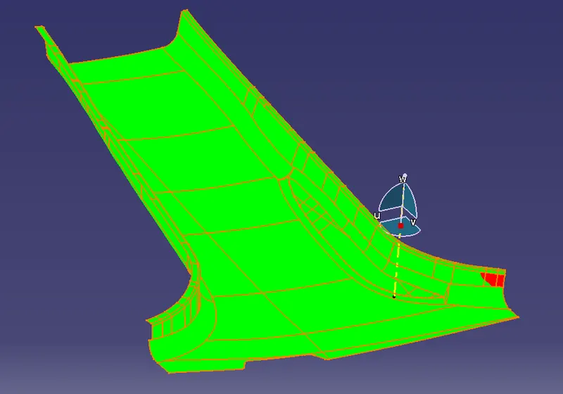
CLASS B FOLLOWING DRAFT WITH MINIMUM DRAFT ANGLE .
CLASS C SURFACE FOLLOWING WITH MINIMUM DRAFT ANGLE.
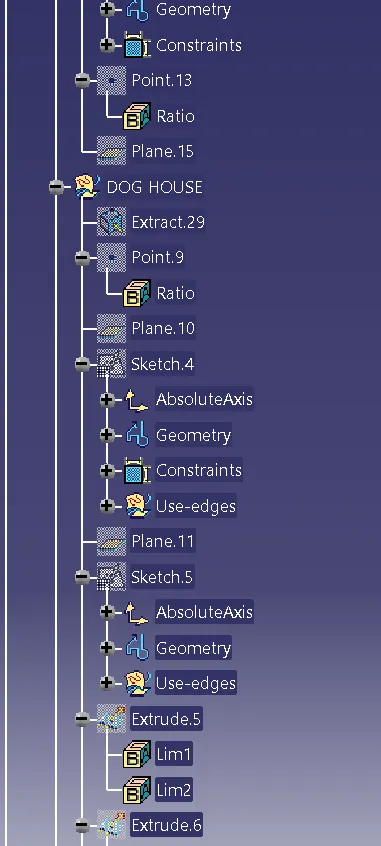
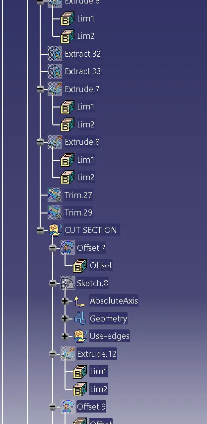
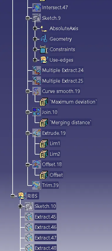
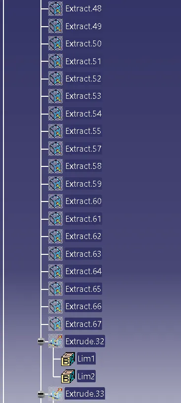
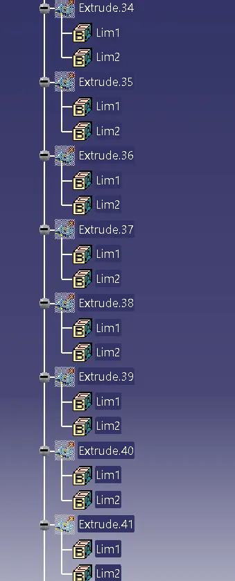
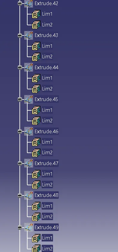
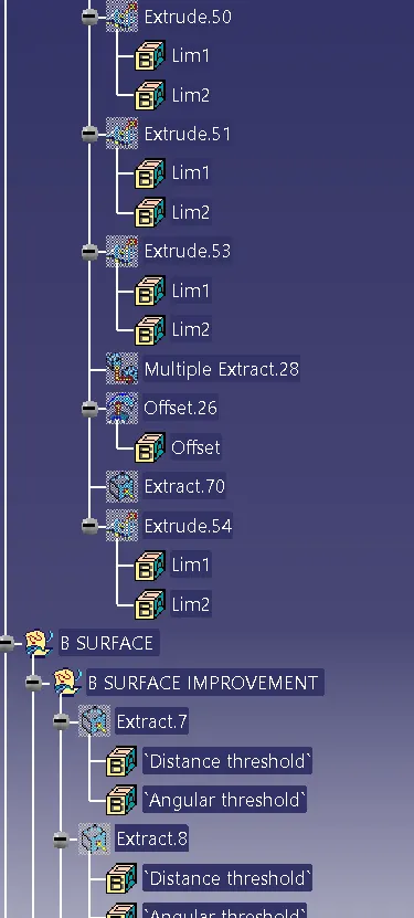
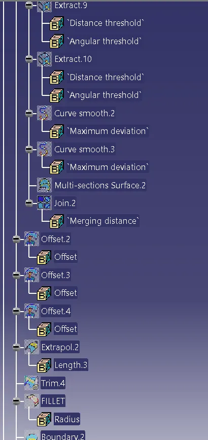
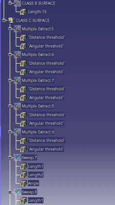
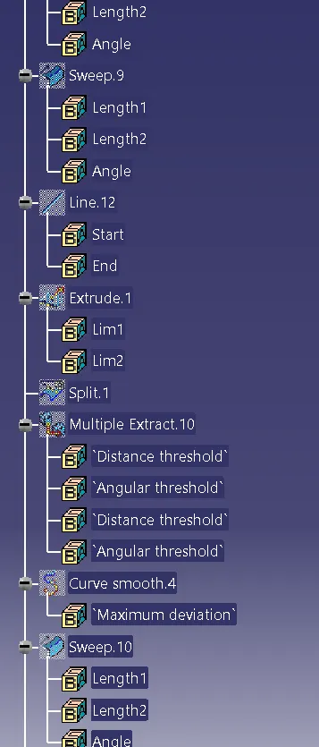
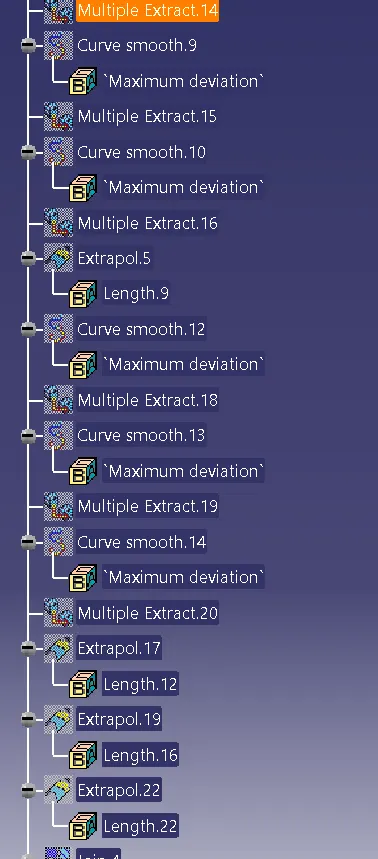
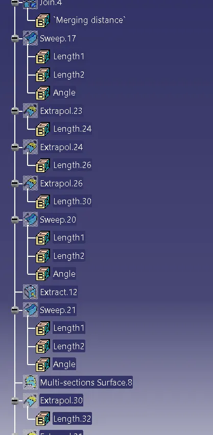
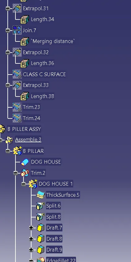
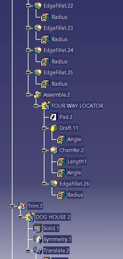
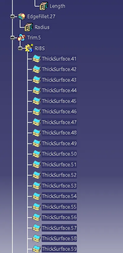
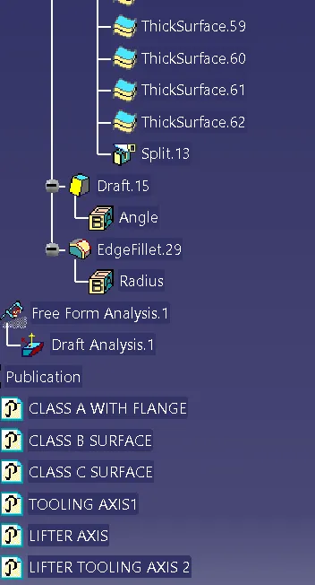
Tree structure of the component.