Week 9 - Project - Master Section Development
AIM:
The objective of this project to develop Closed Surface Model using Master Sections and to develop attachment features for Fixation of Parts by following OEM Design standards and procedures in CATIA SURFACE WORKBENCH and
PART DEsIGN
ABSTRACT
The report details about the Design Life Cycle in Automotive Industry with an practical working model of BPILLAR COVERon the B PILLAR of Car Interior. The report explains the steps followed in creating the tooling axis followed by detail methods in creating B-Surface, Class C Surface and to closed body. The Attachment features creation is also reported by following the design guidelines and finally analysis of Draft to prevent the failure and improve the feasibility of manufacturing the part in plastic injection molding.
DESCRIPTION
MASTER SECTION
Master Sections are the guides for design requirenments which shapes the component after ntechnical styling of Class A Surfaces The body frame is mainly composed of floor longitudinal beams, upper side beams, door sill beams, and front cover, the rear beam, A-pillar, B- pillar, C-pillar and other load-bearing beam structures are composed.
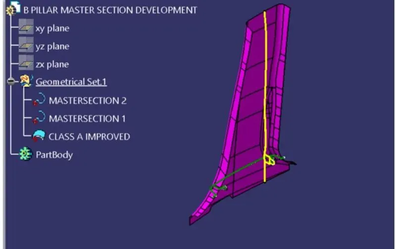
Master Sections are parameterized model of the vehicle body that outlines the guide for NPD Team In this Report B Pillar Cover Creation with detailed procedures of Surface Development and Attachement features are covered
Concept Sketches
Concept sketches are rough idea of free hand sketch obtained through styling team and will be used to prepare the Model. It is usually done through pen and paper and through the painting software. This is will be used to generate the concept for preparing the model by incorporating various styles and information obtained through the stakeholders
CLASS A Creation:
After finalizing the concept the sketches are usually worked in software's such as Autodesk Alias to create Class A Surface
Clay Modeling:
The Class A Surface is concurrently worked by clay modelers to brainstorm and benchmark the styling of the product and later the Concept is validated by bringing up a rough clay model and then it is passed on to the Design team for the preparation of New Product Design (NPD) CAD.
NPD CAD
This where the development of surfaces to parts in CAD kick off and Design engineers involvement is vital in this stage.
The Designers will work on the Input Class A surfaces which are validated from the Feasibility team
The procedure followed in creation of the plastic New Product Design are
- Tooling Axis
- B Surface Creation
- CSurface Creation
- Closed Body Creation
- Draft Analysis
TOOLINGAXIS:
The given Class A input is analyzed to envision the part to manufacture and Tooling axis or Tooling Direction or Die line is the direction that molds pull apart in injection molding. There are two mold pieces names core and cavity. Thus tooling direction determines Mold seperation and also becomes vital in developing the plastic product which is drafted to desired nominal angle for feasible clearance and ejection of final part from the mold.
The Steps Followed in creating Tooling Axis
1. A Reference Point is created along the Surface zero and new Axis system is created
2. The X Direction and Y direction along the Class A were used to create Tooling direction
3. Finally the Tooling axis is created by bisecting the two lines and it is published. Class A Surface as input using surface operation commands Class B is developed
4. The tooling Axis determines the direction of Class C boundary swept with draft direction.
5. When viewing from tooling direction normal all the parts that are drafted should be visible so it gives an rough idea to determine product manufacturing in Injection molding
In B Pillar Model there are Two Tooling Directions one on Main tooling and other on Lifter Side that is used to eject the parts during injection modling Lifter Axis is used because the Attachment feature is bounded by close walls
CLASS A IMPROVEMENT
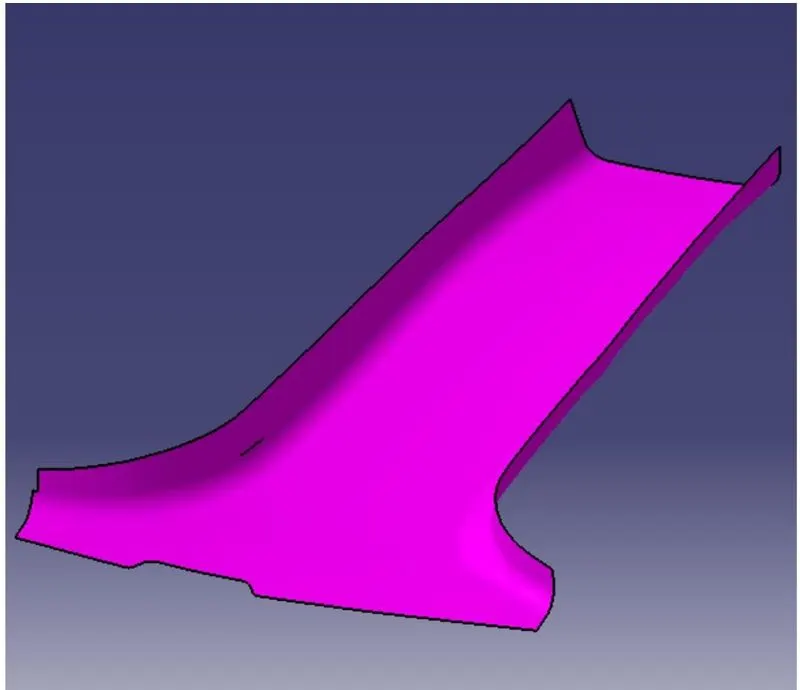
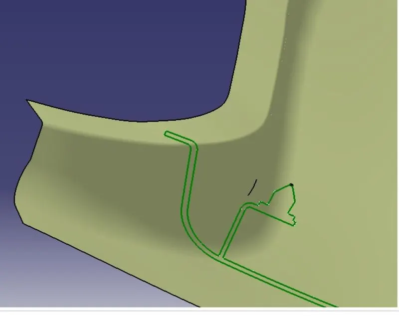
Class A Surface is the outer skin of the product which is purely an aesthetic model with no engineering properties involved The CLASS A Surface has lot of irregular patches and complexity which are inmproved using Mult Section Surfaces and Surface Trims which forms the Improved Class A Input A Tangential Error Propogation method is used to validate the Surfaces using Boundary option. Finally the Class A Improved is used as input Model and is Publihsed
B Surface creation
The next step is to design B surface for the input which is usually the surface where all engineering aspects and support creations are donne.
- The B surface Creation is performed using surface operations in CATIA which is an offset from Class A with dimension proportional to the thickness of the part
- In B Pillar Design the B surface is offset 2mm from the input which is the thickness of the part
- The B surface is an extrapolated surface compared to A surface and forms the
- The Offset Surface leads to Surface Degenerations if
a. Rapid change in curvature or surface continuity
b. Low Radius of CLASS A
c. Conic or styling Fillets
The Remedy is to untrim, extrapolate and trim or create surfaces using Multi Surface Option and Join
Corrected B Surfaces
In this way the Patches are coorected along the B Surfaces and the part is Extraploated with offset of 2mm from A Surface
CSurface Creation
- The Next step is to from the C surface which is an intermediate surface between A and B and is used to give the closed surface appearance to the design
- The C Surface is swept using the profile as boundary line of Class A which is the Guide curve with a subtype along draft direction.
- The Direction of the sweep is the tooling direction formed earlier
- The draft angle for the sweep operation is provided which is 3 Degree and surface is swept for length above the thickness of the specified part
- The C Surfaces must be drafted outwards from the A Side to avoid the parting Line along the A Surface
- The C surface is refined using smooth Curve options to remove the complexity and patches along the swept surface
- Finally the Class A and Class C surfaces are joined together and connexity of surfaces should be less than 0.003mm and the surfaces are merged.
CSurface merged with Class A
Closed Body Creation
- The merged surface is then trimmed with B surface to form the closed surface.
- The Closed surface is then validated to find the irregularities along the edges and imperfections along the edges were then corrected using operation like extrapolate C Surface Creation
- The Direction of the sweep is the tooling direction formed earlier
- The draft angle for the sweep operation is provided which is 3 Degree and surface is swept for length above the thickness of the specified part
- The C Surfaces must be drafted outwards from the A Side to avoid the parting Line along the A Surface
- The C surface is refined using smooth Curve options to remove the complexity and patches along the swept surface
- Finally the Class A and Class C surfaces are joined together and connexity of surfaces should be less than 0.003mm and the surfaces are merged.
CSurface merged with Class A
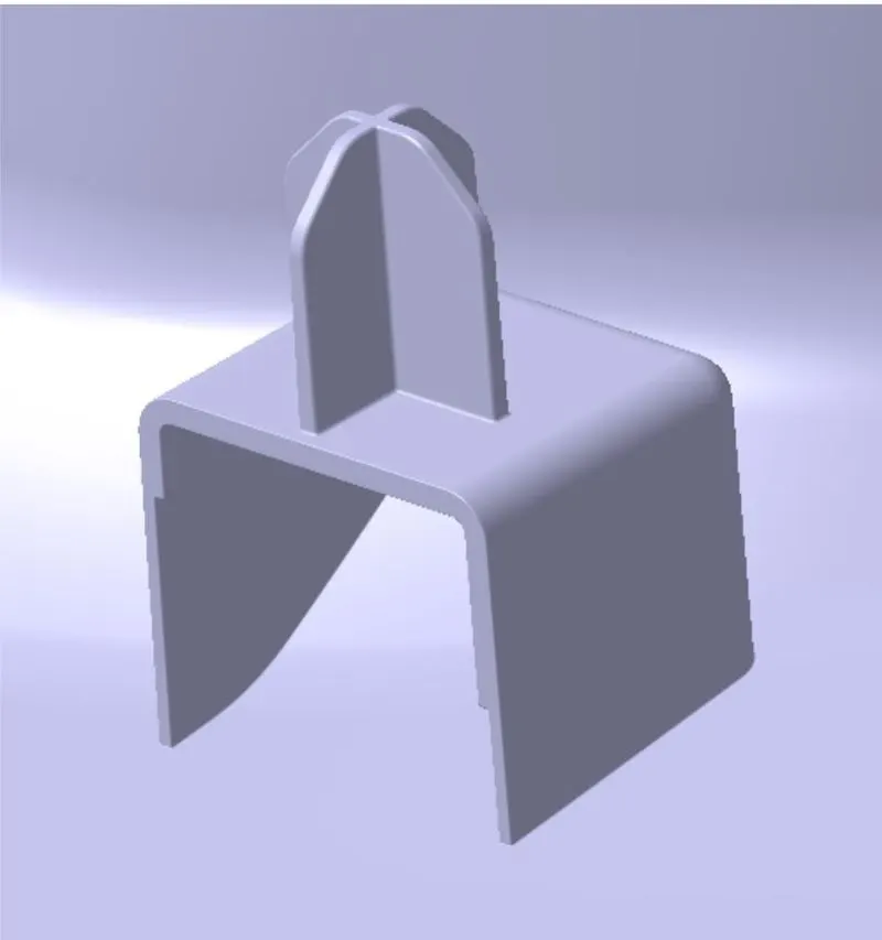
DOG BOX:
Closed Body Creation:
- The merged surface is then trimmed with B surface to form the closed surface.
- The Closed surface is then validated to find the irregularities along the edges and imperfections along the edges were then corrected using operation like extrapolate
RIBS
Ribs provide stifness to the parts and can be to impart thougness whthout increasing the part thickenss and are locators and provide allignment to the mating parts The Design Rules for two way and four way fixtures are
- Rib Wall Thickness should be 0.4 times off Thickness of the part
- The Drafted walls of rib should be within 0.5 degrees
- The top height of rib should be at least 0.70 mm thick to allow the molten plastic to reach the top to avoid Short Shot
- The Thickness of the Rib, Fillet Radius, Draft and rib root thickness are measured and are withing the design specifications Draft Analysis Procedure
- The part created has to be changed to material mode in display frame
- Then by enabling compass definition the axis system is pan along the direction of the part and aligned in line with the tooling direction
- Lock Direction is applied that fixes the compass and then the mode dialog box is formed by snapping at any point on the part
- The Color Codes are classified and Draft Angle are applied
- Then the Running point analysis is used to hover around the part to analyze the permissible draft angles and the analysis is Saved The Analysis is provided below
DRAFT REPORT:
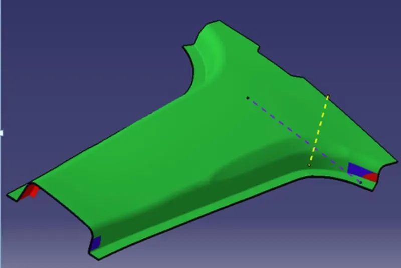
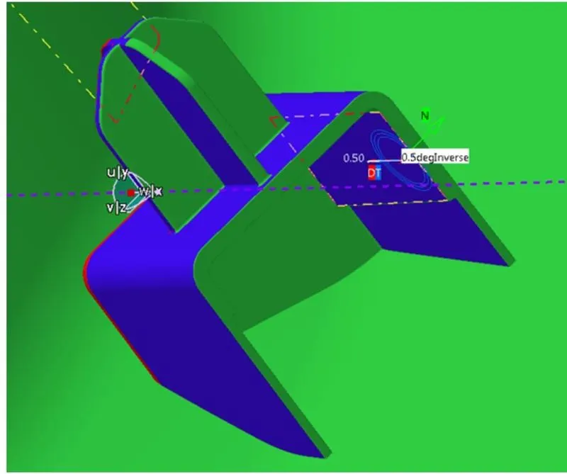
The Draft Report for B Pillar Model is shown Below
RESULT:
- The Green color is drafted walls above 3 degree
- The Blue color is drafted walls from 0-3 degree
- The red surfaces are negative degree The analysis shows the drafted walls are above the par of 3 degree which is permissible to manufacture in the injection modeling
- The Running point analysis hovered along the drafted walls show parts are above 3 and will be easily cleared from ejection.
- The Areas in Negative Tooling that falls short to the permisble design Rules are shown
- These surface are corrected using Surface Operations and generaly in OEM Class A Improvement requires prior approval from Styling team and the draft report and analysis is used to get approval
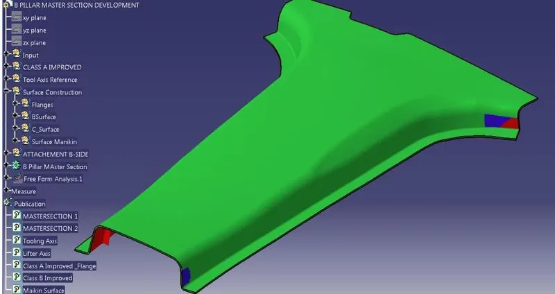
- The Tree Structure are Classified and the important features are published and the operations are rendamed and classified into geometric subset shown below.
- The 2D Sketch created for this operation arepositioned sketches projected through a point and all geometries are fully constrained
CONCLUSION:
Thus a Tooling Axis is created and a open aesthetic Class A Surface is developed into a closed surface with all plastic design rules and a final part body is created out of it in CATIA Surface Work Bench. The Design is then validated with Master Section and understood the use of Master Section Development in Product Design through development of B Pillar Cover used in the Car Interiors.