Week 8 - Challenge 1 - Draft Analysis on a Fan Cover
DRAFT ANALYSIS:
- It is a tool that allows the user to ‘see’ whether the part they are designing can be removed from the tool being used to make it.
- In the case of plastic injection molded parts it also allows the designer to see if there is enough draft on the part to ensure that it can be correctly grained.
- I always use the tool with the axis direction method. Put the main axis on the draft direction line with Z being parallel to it. Select the tool then select the part body. You may need to reposition the axis again. The results window has 2 options 1 with just 3 colour variants and the other with many variants.
- They can be edited by double clicking on them to give you the result you desire. The colours show the different draft angles
- The Draft Analysis command enables you to detect if the part you drafted will be easily removed. This type of analysis is performed based on color ranges identifying zones on the analyzed element where the deviation from the draft direction at any point, corresponds to specified values.
- The draft analysis button within CATIA V5 will help you quickly gather the draft angle on multiple surfaces without the need for tedious manual measurements. Here is a quick rundown of how the icon works when you have a given die direction.
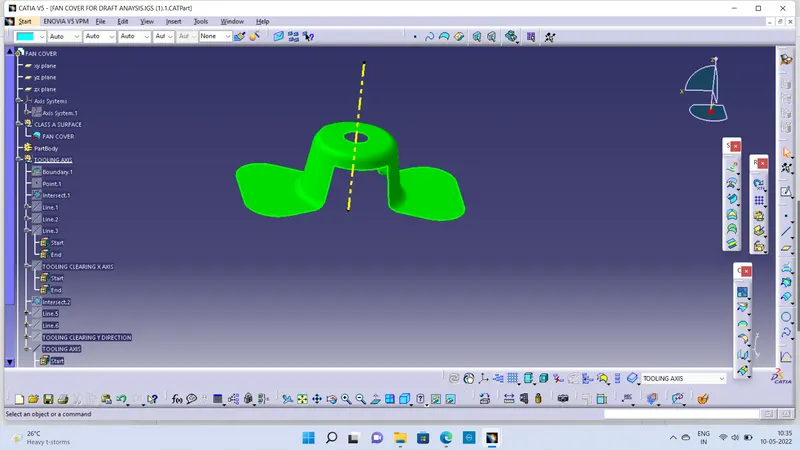
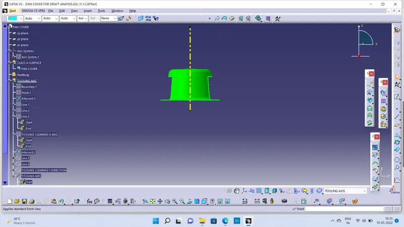
- For the purpose of this demo, I have a part with several drafted surfaces that are oriented in-vehicle location (i.e. not perfectly aligned with x, y, or z-direction) as seen in Figure 1. The die direction is indicated by the dashed red line.
- Note that the draft analysis initially assumes a Z-axis direction. The incorrect draft analysis Since our part was created in vehicle location, we must first fix the default direction that CATIA assumes. This can be done with the dragging of the compass (fast method) or by creating an axis system with respect to the die direction (requires a little more leg work).