Week 9 - Project - Master Section Development
AIM:
To create a solid body of B pillar cover including ribs and locators using given A-class surface and master section and adding thickness.
INTRODUCTION :
B-Pillar
The B-pillar is the central pillar of the car. This pillar is actually a sheet metal part which is welded in the BIW of the car. The B-pillar trim is attached to the B-pillar and improves the aesthetic look of the car. Mostly the trims are manufactured by the injection moulding process. The design of the B-pillar is carefully done to make the part manufacturable and usable in the interior. While manufacturing a part through injection moulding a lot of defects can occur on the plastic part which will destroy the look of the panel. The design has to make in such a way that all the errors can be rectified
MASTER SECTION: These are the guidelines provided to a design engineer which describe how a component would look once it is modelled into a solid component from the class-A surface. For example, in this model, we have received master-section as an input which tells us about the thickness of the component and the dimensions & type of the engineering features on the component.
PROCEDURE:
CREATING TOOLING AXIS
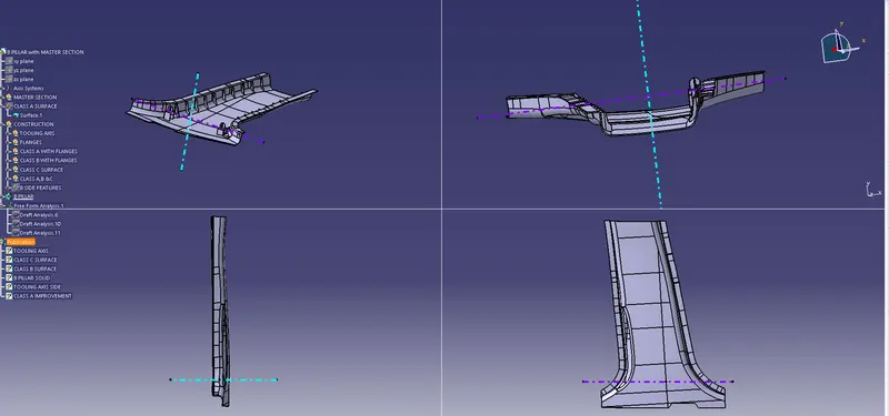
In this model, we will need two tooling axis. One main tooling axis and the other will be for the inside surfaces of the dog house. This will be our lifter tooling axis. Create a point as the centre of the class A Surface and create a line in point to a direction for the creation of the tooling axis. As the position of the tooling axis does not matter, we have taken the master section as the reference to make a point and a plane.
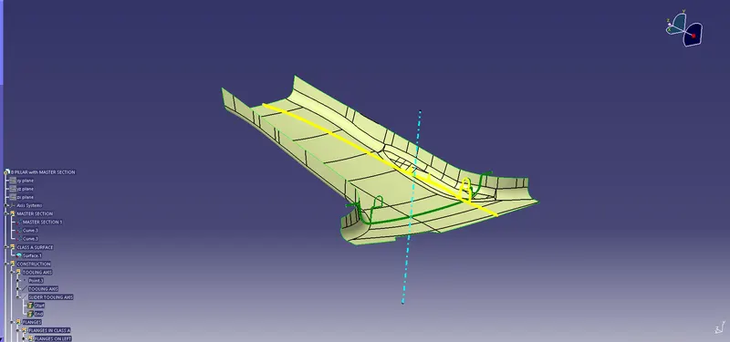
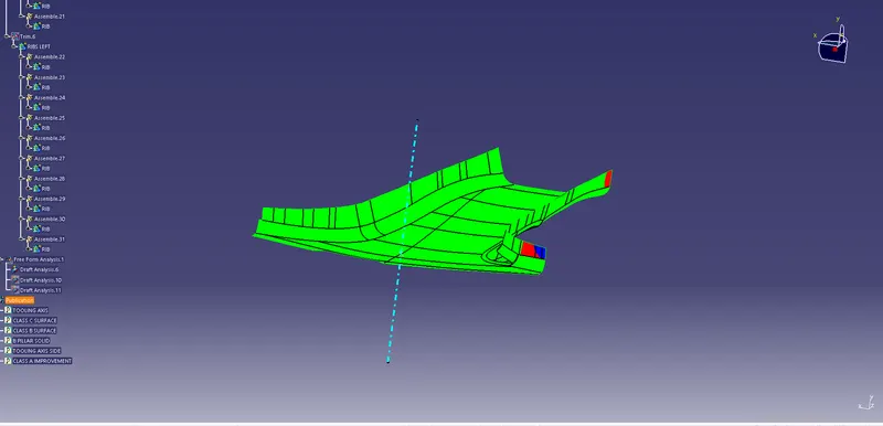
Analysing draft angle for Class A surface with respect to tooling axis and checking if there are any negative and zero angle in the given surfaces. Resolve the created tooling axis and make it proper.
3) A Class Surface
In automotive design, a class A surface is any of a set of freeform surfaces of high efficiency and quality. Although strictly, it is nothing more than saying the surfaces have curvature and tangency alignment – to ideal aesthetical reflection quality, many people interpret class A surfaces to have G2 (or even G3) curvature continuity to one another. Class A surfacing is done using computer-aided industrial design applications. Class A surface modellers are also called "digital sculptors" in the industry. Industrial designers develop their design styling through the A-Surface, the physical surface the end-user can feel, touch, see etc.
CREATING FLANGE
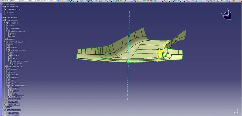
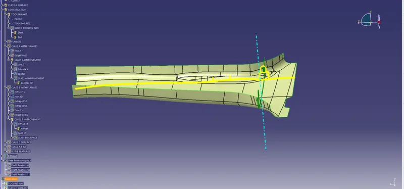
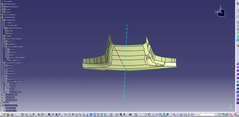
When we observe the master section properly, we will find that class-A has some projection outwards which is not in the input. So we have to create these flanges on class-A on both the sides, taking the master section into consideration as it contains all the descriptions of the flange. Once we make flanges on both sides of the surface, we can offset it and trim it with a class-B surface too. A simple approach is followed to make the flanges:
- Extracting the respective boundary of class-A surface and then using smooth curve tool.
- Sweeping this curve with the reference surface as class-A surface (make sure it is extending on both sides of class-A, this will reduce our time of creating extrapolate later).
- We have to put different values for the draft till the flange matches the master section.
- Once this is done, we get our flange. Offset it by 2mm downwards for class B.
- Trim them with their respective surfaces.
While making a flange on one side we observed that the class-A surface and master section are not matching at one point. Here we made a flange as parallel to the master section’s flange as possible and then made an offset of that flange. Later we trimmed it with the class-A surface. On this side the offset was our original flange, so for class B, we made an offset of this surface. the lines make are the intersection of the flange and class-A surface which clearly are not in line with the master section as in it the lower line represent the same. The lower line is a parallel curve to the flange where we want the flange to be, so we measured the distance between the two and made an offset to that distance.
4) B Class Surface Creation
Represent internal and functional surfaces. This cluster exemplary includes derived surfaces created by offset operations from class A surfaces to define the thickness of the material. In this file, it is important to link class B surfaces geometrically to enable an adaptation to class A surfaces automatically in case of styling change.
After creating the tooling axis, B surface is to be created which is nothing but the surface parallel to the A surface. B surface contains all the fillets and the edges which the A surface contains.
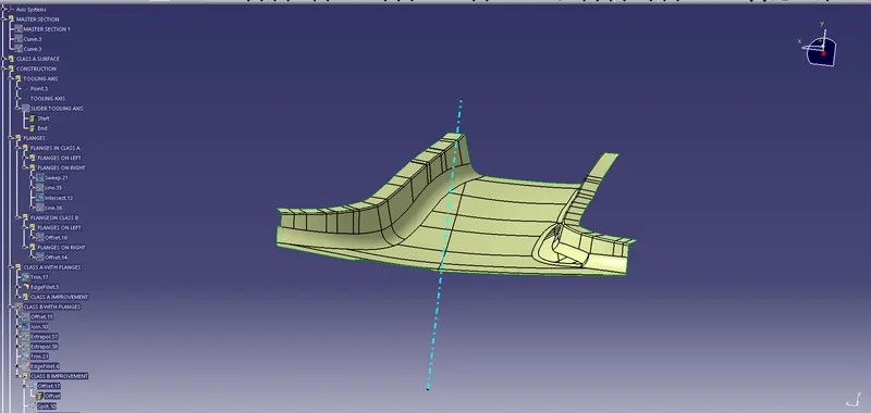
After the creation of the class B surface, trim the surface by offsetting the flange from the class A flange and fillet trimmed edges.
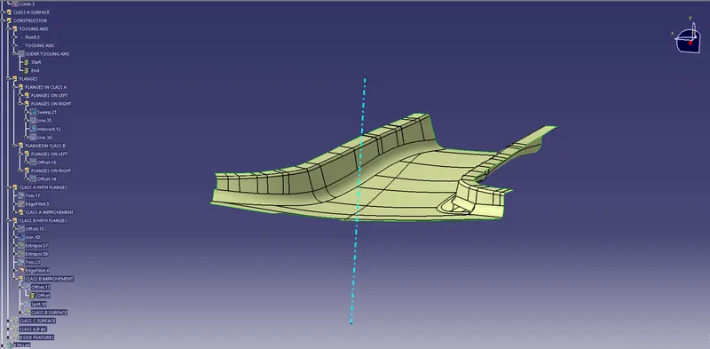
Improved Class B
5) C Class Surface Creation
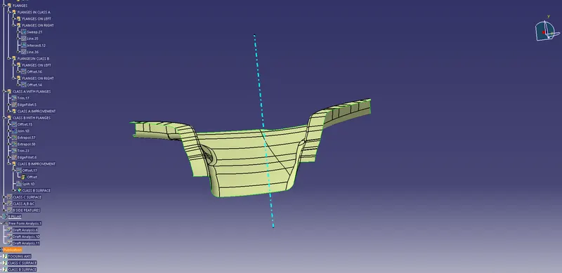
Class C Surface is swept along the boundary of Class A at an angle perpendicular to the CLASS A surface with respect to the tooling axis direction with a draft angle of 3 degrees. Some of the edges look curvy so that edges make a sweep in near flat edges and extrapolated up to intersect with other swept faces.
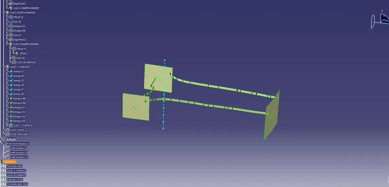
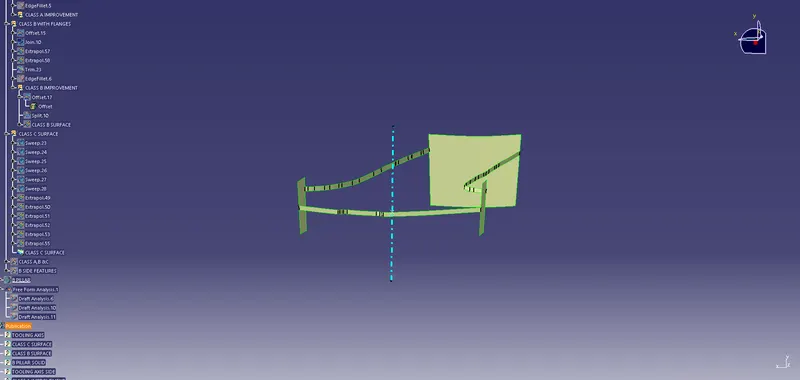
After the creation of three surfaces, first, trim with class A surface and Class C surface and check the trimmed edges are proper join with two surfaces.
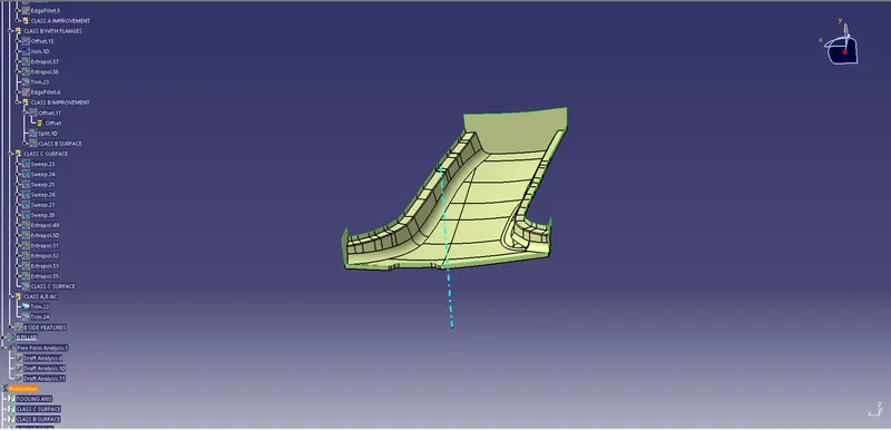
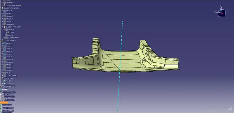
Trim the Class B Surface with trimmed class A and C surfaces and check with the boundary tool, whether the surface is fully closed surface or not.
DESIGN RULES FOR RIBS:
- Draft: 0.5 deg per side (minimum), but this value should not be high enough that it will cause failure for other considerations. For example, more drafts will result in less thickness at the top surface.
- The thickness of ribs: 40% of wall thickness or 0.4*t where t is the wall thickness.
- Height: ≤ 5 times the wall thickness i.e. 5*t
- Spacing (for more than 1 rib): 3:1- steel height/width ratio (maximum). h/w =3or2(preferred) where h is the height of the rib and w is the space between two ribs.
- Minimum thickness at the tip: 0.75
- Radius: 0.25mm max
- Ribs on the opposite side of the wall should be offset
- Ribs should be connected to other structural features where possible.
- Rib root thickness should not be more than 30% of the wall thickness.
DESIGN RULES FOR DOG HOUSE:
- Minimum height: Less than 6mm causes steel condition.
- 3:1 ratio of steel width to height. But 2:1 is preferred.
- Minimum width: 3:1 ratio of steel width to height. But 2:1 is preferred.
- Draft: minimum 1.5deg.
- Sink saver: height (C) = 40% of nominal thickness. Width (B) = 3.0mm-6.0mm.
- Optimal radius:25mm
NOTE: The design rules for designing a 4-way locator pin are the same as that of ribs design rules.
CREATION OF DOG HOUSE
From the given Master sections 1&2, Project the Master section 1 and extract the dog house projection.
Create a point at the centre on the inner line by Point definition as shown and create a plane with reference to the point in the ZY plane and then draw the sketch-like dog house and extrude the inner lines from the sketch using Extrude option.
Create a plane with reference to the point in the XY plane and extract the Master section 2 Project the Master section 2 and extract the dog house projection to create the front wall and back wall and then trim the surfaces to create the dog house surface as shown.
Thicken the extruded surface by using the Thicken option in the Part body.
Split the Dog House at the front with the wall in the Part body.
Now create the inner trim for the Dog House by offsetting the side walls to 1.2mm as the ‘C’ should be 40% to the Main wall thickness and offset the B surface in the region of the dog house to 3mm distance upwards as the ‘B’ distance from the B Surface is 3-6mm for Dog House.
Now intersects the offset surface with the back wall to create the feature of B surface as shown and extrude the line and then trim with the sidewall and then offset the trim to 1.2mm inside as shown.
Fillet the edges of the trim to the specified radius. Split the Part body of Dog House with the offset Feature trim in the Part body.
Fillet the Dog House of radius 1mm inside and 3mm outside.
Create the tooling axis for Lifter using the ZY plane
CREATING LOCATOR:
Project the lines of the Master sections 1&2 to create the limits of the locator onto the plane of ZX and then draw the sketch for locators and then Pad it in the Part body to a height of 20mm as given master section.
Draft the faces and Chamfer the edges at the top and Fillet the edges.
Attach the locator with the Dog house using the union trim option and symmetry the Dog house part with respect to the master section.
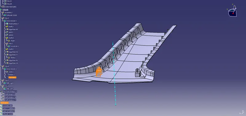
CREATING RIBS:
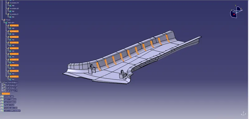
Create a sketch on the ZX plane to create ribs. Maintain the distance of 50mm in between the ribs. Extrude the sketch and thicken it to 0.4 times the Main thickness.
Cut the ribs by extracting the b surfaces which ribs lay in the b surface and offset to 10mm. split the ribs with an offset surface.
Translate the ribs with a 50mm distance in between on both sides. Split the ribs with Class A and 10mm offset surface of Class B surface. Union trims the ribs with the Main part body. Draft the ribs and Fillet the edges.
DRAFT ANALYSIS:
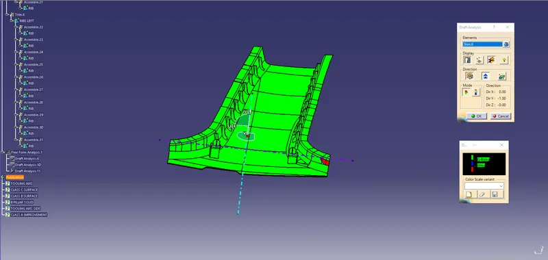
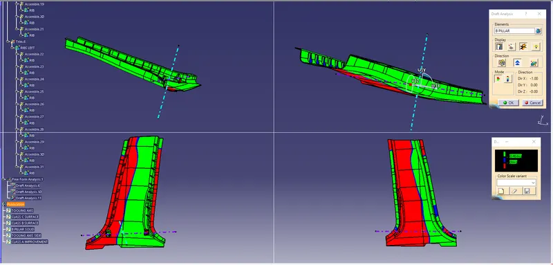
Generate the draft analysis for the Tooling axis and slider axis.
First, we analyse the draft with the tooling axis as the angle must be 2.8 degrees and considered as 3-degree from the A-side of the part body. Here Draft analysis in the isometric view.
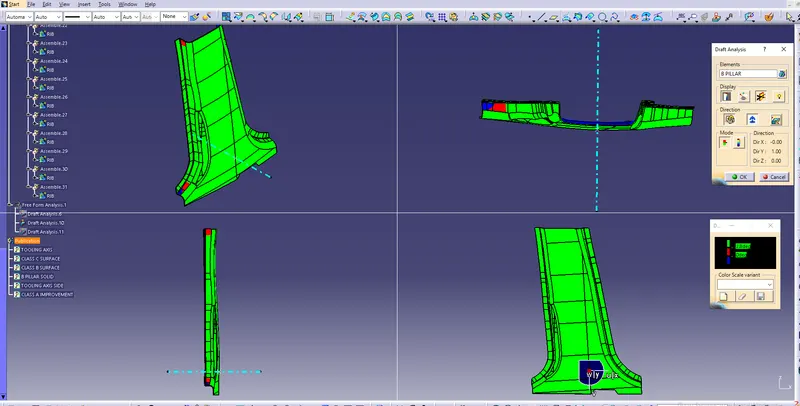
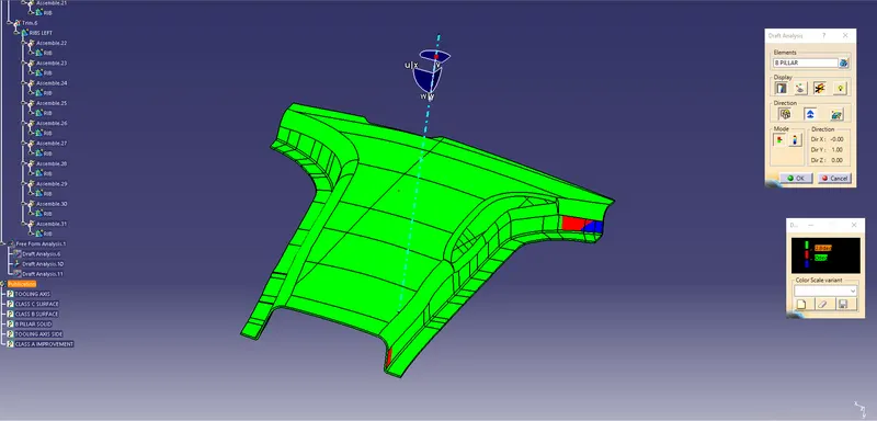
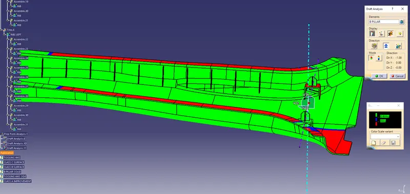
Then, analyse the draft for Engineering features like Dog house, Locators and Ribs with slider axis.
On the B side, the feature draft angle must be 0.5 degrees.
B PILLAR COMPONENT:
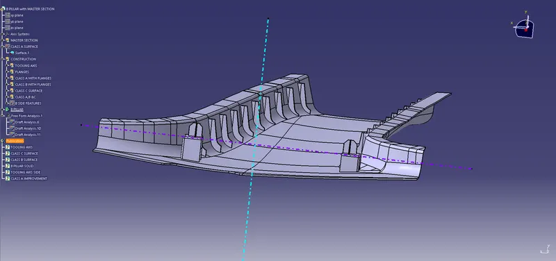
Isometric view of B pillar Component with Engineering features.
CONCLUSION: Hence we created the Plastic design and the Engineering features from the Master Sections and did the Draft Analysis for the given B Pillar Class A model and Final Component.