Week 8 - Challenge 1 - Draft Analysis on a Fan Cover
AIM : To create the tooling axis for the given Fan cover model meeting the requirements of the draft angle and perform the Draft analysis on the model.
Importance of Draft angle while designing plastic components :-
A draft angle refers to that slant applied to the sides of most features of injection molded parts. Positioning of the injection angles is such that they run towards the direction of the mold’s pull and parting line. They help to release the molded parts from the mold easily. 99% of your injection molding design will require draft angle injection molding for a successfully made part.
When developing parts for plastic injection molding, applying draft (or a taper) to the faces of the part is critical to improving the moldability of your part. Without it, parts run the risk of poor cosmetic finishes, and may bend, break, or warp due to molding stresses caused by the plastic cooling.
Many a times, draft angles may create a conflict of interest. Molders like and recommend draft angles. However, mold-makers find it daunting to machine the angles on all cavity and core surfaces. Some also believe that draft angles may complicate the part designing.However, it is crucial to note that draft angles offer an extensive range of benefits. They are vital to ensure that molded parts meet the required quality standard. Without a draft, you increase the chances of having injection molding issues. This may unnecessarily increase the cost of production and lead time.Problems often arise from friction and vacuums when there is no draft designed into the part. These can damage your part. In extreme cases, the mold is also affected. Plastics shrink before cooling. Therefore, some portions of your part will likely pull away from the mold. Other portions will grip the core.
A draft angle allows you to use a simple push on the ejector pins to pop your part out of the mold. This way, you will prevent the part’s surfaces from being dragged along the mold when ejected. Friction between your part’s surface and the mold’s surface can cause scratches and affect your part’s appearance.
PURPOSE OF DRAFT ANALYSIS : The Draft Analysis command enables you to detect if the part you drafted will be easily removed. This type of analysis is performed based on color ranges identifying zones on the analyzed element where the deviation from the draft direction at any point, corresponds to specified values.
No parts can be ejected from the tool if it is having a straight 90 degree profile from its base surface. A small draft angle is provided to each and every area of the component in order to get an easy removal of the component from the tool. Draft analysis technique is used to analyze whether our part model created in cad is manufacturable based on the draft condition applied. Here the part should get easily removed from the panel dies (in case of Sheet metal part) or Mold (in case of plastic). Here we are providing a direction in which components should eject inorder to get an easy removal of components from the tool. In other words it also lets us know whether the model is having a draft angle and how much is the draft angle from the tool direction.The major consideration of Draft Analysis is whether sufficient Draft Angle is provided on the component. Components while designing should be provided with a considerable amount of draft angle depending on the manufacturing consideration. For Plastic components we provide a draft angle of 3degree(Draft angle of 0.5 is given ideally to the features inside the plastic part). But for Automotive Sheet Metal Parts, it will be from 7 degrees or more.
To detrmine Ideal Tooling Axis to do the draft analysis
For performing Draft Analysis we need a tooling axis , i.e basically the direction in which the mold opens. In Molding machine arrangement is given to open the mold along a direction which is known as Tooling Direction. In other words. The mold is built from two separate halves (Core and Cavity) and tooling direction basically define the direction of mold pulls apart.
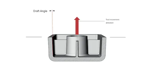
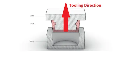
This task shows how to analyze the draft angle on a surface. The Draft Analysis command enables you to detect if the part you drafted will be easily removed.
VARIOUS STEPS PERFORMED FOR DETERMINING TOOLING AXIS AND THEN DOING DRAFT ANALYSIS ON THE SURFACE OF THE FAN COVER
1. We opened the Class A part file in catia and change the workbench to Generative Shape Design and check for any gaps between the class A surface using Join tool and also check for any discontuinities using Boundary and Disaasemble tools.
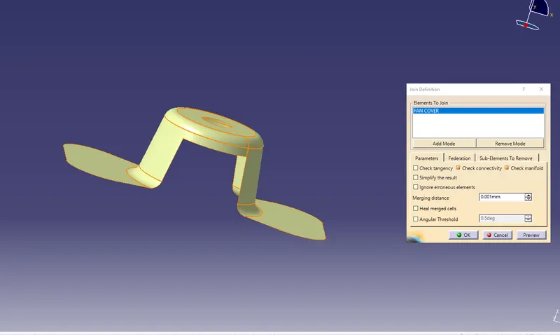
2. There are different methods to find out the tooling direction. Here we are using bisecting method to find out tooling direction. We can use any method,but our main aim is to reduce the cost of manufacturing by reducing the complicity in manufacturing the component. Here, we are using bisect method to find out the tooling axis for fan cover
- The first thing to do is finding out the possible tooling direction by visually checking the part. Rotate the part in all direction and find out the possible direction for tooling axis. Here in this case viewing from Z direction we can clear the face in tooling.
- Then we create a point on the surface of the part, we can create the point anywhere on the surface.
- Most of the cases we create the point in holes and pocket of the part,because the holes and pockets is to create a problems when we do the draft analysis,so we create a point in mid of the hole to create a line on this point along z direction named as DUMMY TOOLING AXIS. On this point we put a new axis system.
- Then we are finding out the tooling axis in X direction. For that intersect command is used to get the boundary in X direction.
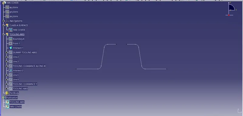
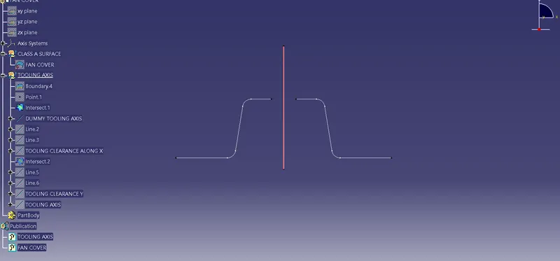
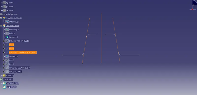
- Then we create the lines on the walls because it is not cleared with dummy tooling axis and the bisect these two lines with the line bisect command and a bisected line is created name as tooling axis in x-direction
- Then we are finding out the tooling axis in Y direction. For that intersect command is used to get the boundary in X direction.
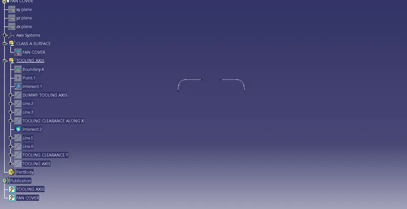
- After this we create the lines on the walls because it is not cleared with my dummy tooling axis. and the bisect these two lines with the line bisect command and a bisect line is created name as tooling axis in Y-direction
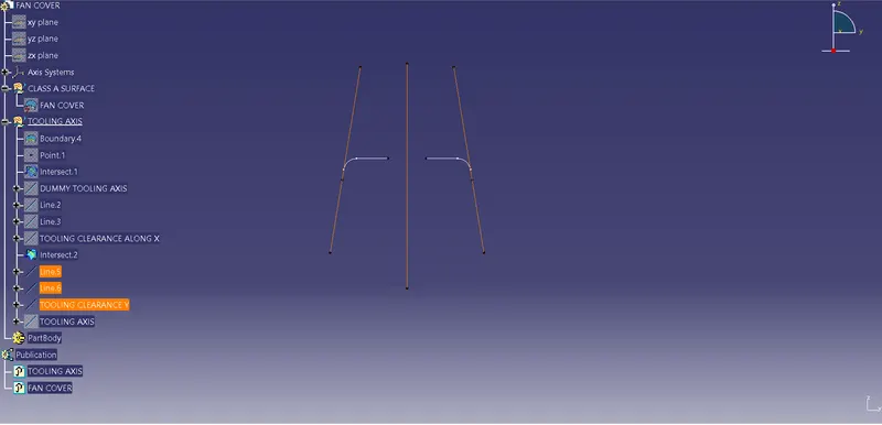
- After this we bisect the lines named as tooling clearance along x and y to get main tooling axis
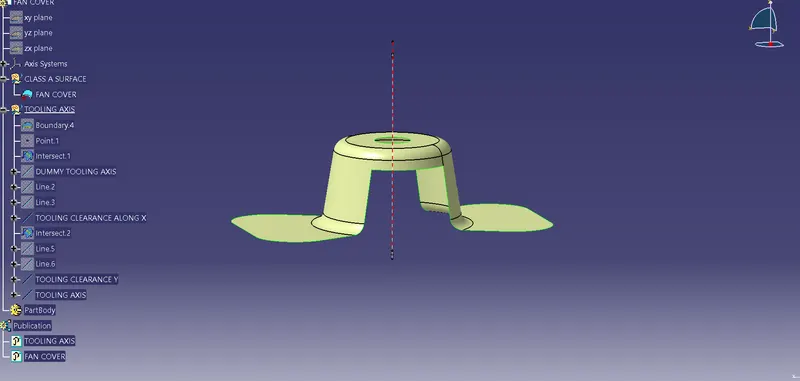
Since we have determined the ideal tooling axis , we will now perform draft analysis on the fancover to determine if the given surface is ideal for molding
- To perform the draft analysis the view parameters are first set to material mode.
- Then go to Insert >>analysis>>feature draft analysis the following window will appear
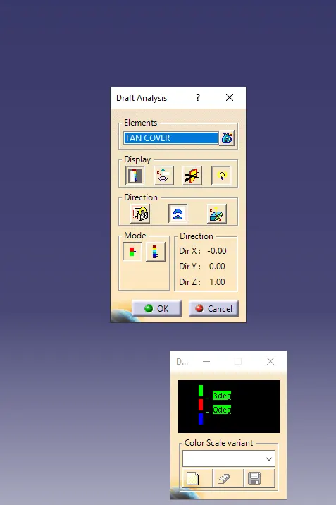
- First, select the axis system and drag the axis system to the tooling axis and lock the orientation. This axis system defines the draft direction according to the tooling axis.
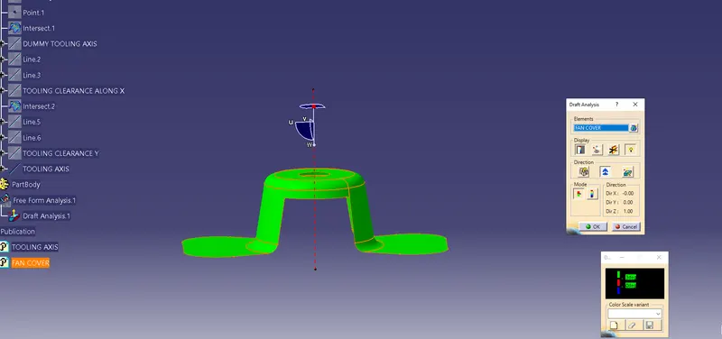
- Switch on the color scale and set the draft value 3° using colour scale. and it will be displayed in green color. Any draft angle below 3 degrees will be shown in red color.
- Here, the compass direction is rotated to have the positive direction in the maximum portion of the part. Then the compass is locked in the orientation and a new tooling axis is created using the compass as the direction.
- Now select the running point tool to measure the draft angle at the various locations and then if all surfaces pass the draft analysis switch on the light effect that will show the component in green color if the component has the required draft angle.
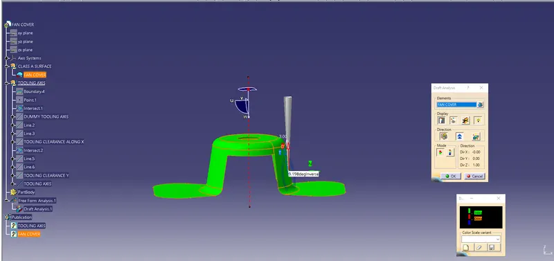
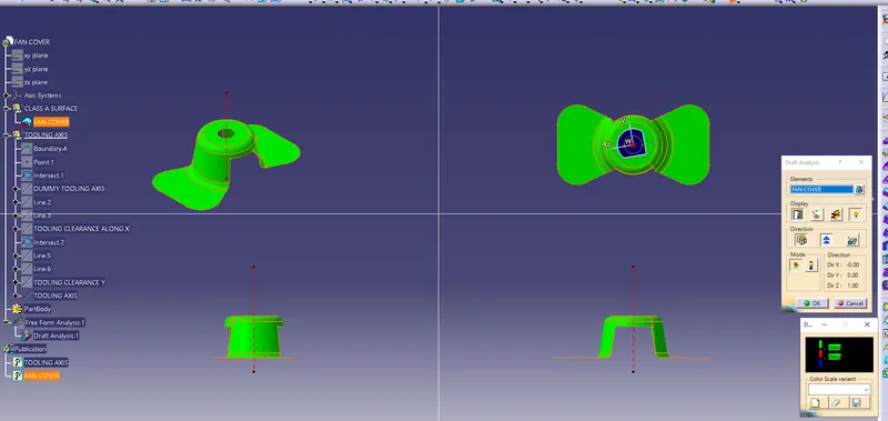
Conclusion:Hence created the tooling axis for the given Fan cover model meeting the requirements of the draft angle and perform the Draft analysis on the model.