Week 8 - Challenge 2 - Base Bracket Design
AIM: To create the Base Bracket Plastic component through the given Class-A surface and to create tooling axis for class A surface and do draft analysis on both class A and the final closed model.
OBJECTIVES:
- Creation of tooling axis using bisecting method
- Creation of class C and Class C surface
- Creating a solid part out of surface modelling
- Draft Analysis on Class A and final plastic component
Introduction: In this project we are designing a base bracket using given class A surface. We approach it by creating class B surface keeping in consideration with component thickness. then we proceed with creation of class C from given parent surface with proper draft.
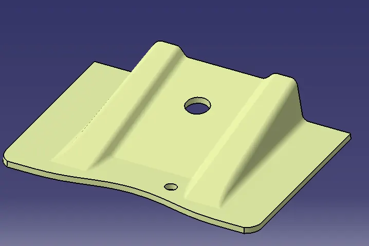
Class A : Following surface has been given as input for component creation. It describes the final production surface data for the aesthetic parts of a component which will be visible .
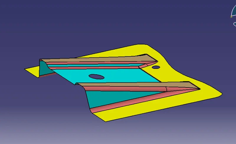
CREATING TOOLING AXIS FOR THE BASE BRACKET OF CLASS A USING BISECTING METHOD:
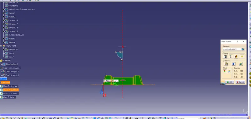
1. Creating dummy tooling axis and then using bisecting method to determine the actual tooling axis. Here we first determine the best tooling direction and then accordingly we created an intersection of class A surface with YZ plane to get main tooling axis . Basically tooling axis is created by bisecting the lines drawn on the drafted surface
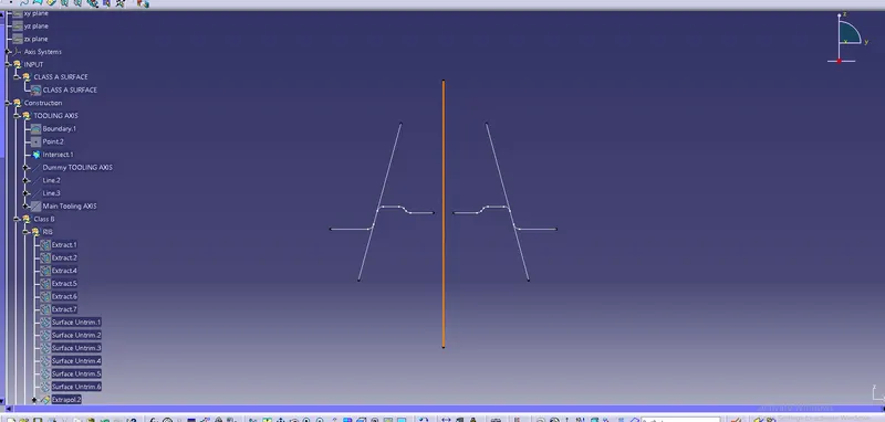
Here, line shownis dotted red color is the main tooling axis
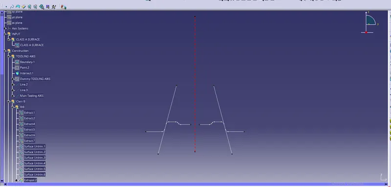
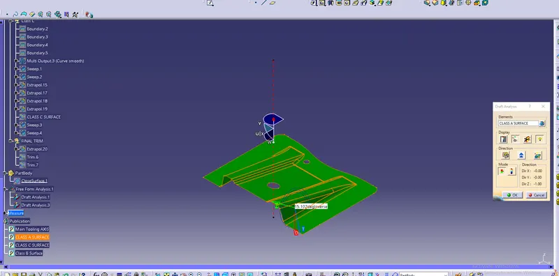
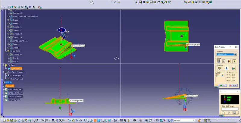
Draft analysis on class A : After achieving the main tooling axis we go on to do the draft analysis on class A surface to check whether it can be used to manufacture main component or not. For plastic components the draft angle should be 3 degree or more than it .
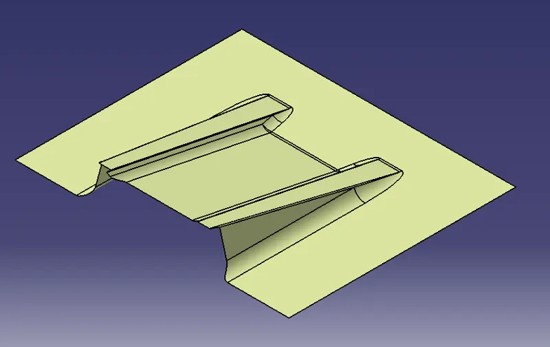
Creation of Class B :
- For class B creation we have extracted the surface from class A and using untrim to obtain original parent surface.
- We then extrapolate the surfaces and giving offset as per thickness of component.
- After offsetting ,all the surfaces are trimmed in the required shape as per class A.
- Required fillets are then given to the surfaces.
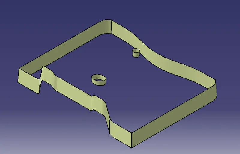
Creation of Class C Surface :
- For creating this surface which lies between class A and B we first extract the edges of class A using boundary option.
- Now we sweep this boundaries along the draft direction which is the direction of main tooling axis with 3 degree draft
Final close component creation :
Finally, we join class A and C and then then perform final trim between A&C and B surface to get a closed final component.
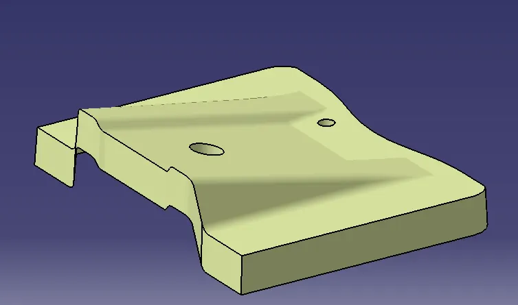
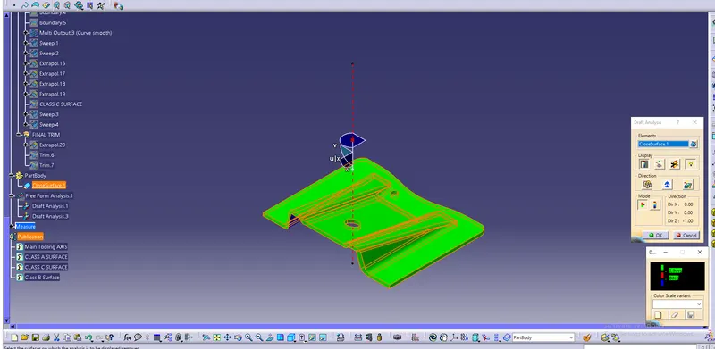
Draft analysis on the final base bracket part : Here we do final draft analysis and reach the conclusion that the following plastic part is manufacturable as it has positive draft with respect to main tooling axis
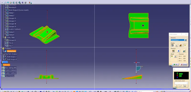
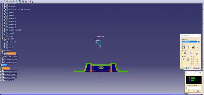
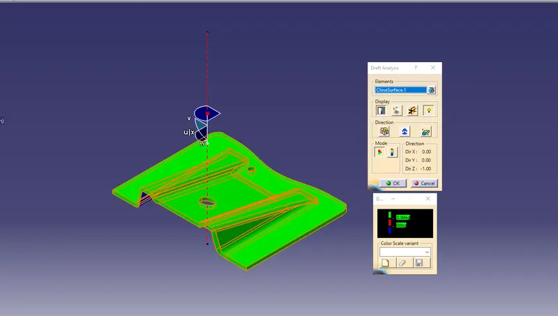
Conclusion: Hence we have created the final component using the given Class A and performed draft analysis on class A and final component and concluded that the base bracket with given class A is manufacturable.