Week 9 - Project - Master Section Development
Aim:
To create a solid body of B pillar along with necessary engineering features- ribs and locators using catia v5 tool for the given A class surface and master section.
B-Pillar Introduction:
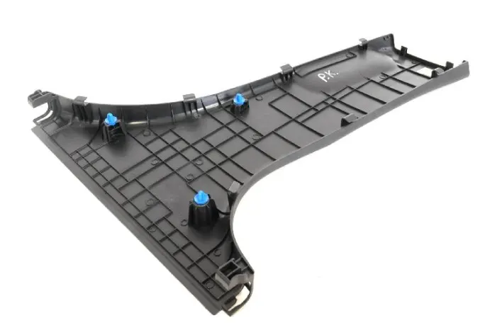
The B-pillar is the central pillar of the car. This pillar is a sheet metal part which is welded to the BIW of the car. The B-pillar trim is attached to the B-pillar which improves the aesthetic look of the car. Mostly the trims are manufactured by injection molding process. The design of the B-pillar is meticulously done in order to make the part manufacturable and usable in the interior part of the car. In manufacturing process the part can be subjected to defects. Therefore,The design has to made in such a way that all the errors can be rectified.
ABSTRACT:
The report describes the design/approach of design methods followed in the industries. In this model we have to create a close solid body from the given class A surface.Then we work on the engineering B side features considering the design rules followed in the OEMs on the B-side feature creation of the model. The overview of the approach followed is mentioned below:
Check for any defects or irregularities in the given class-A surface.
Making a tooling axis to perform Draft Analysis.
Performing the draft analysis on the given class A surface and in case any faces that do not have drafts,then those can be corrected by the class-A designer.
Understanding the master section given.
Creating the flange on both sides of the class A surface(correcting the irregulaties of the class A surface).
Create the class-B and class-C surfaces.
Creating the surface model by trimming the surfaces A, B, and C together.
Close the model by giving thickness.
Creating the B-side features.
Performing the draft analysis on the final model.
DESIGN RULES FOR RIBS:
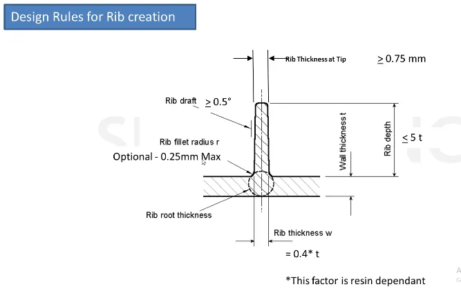
- Draft: 0.5 degrees per side (minimum), but this value should not be high enough in order to cause failure for other considerations. For example, more drafts will result in less thickness at the top surfaces.
- The thickness of ribs should be 40% of wall thickness or 0.4*t where t is the wall thickness.
- Height:≤ 5 times the wall thickness i.e. 5*t
- Spacing (for more than 1 rib): In 3:1 ratio- steel height/width ratio (maximum). h/w =3 or 2(preferred) where h is the height of the rib and w is the space between two ribs.
- Minimum thickness at the tip is 0.75
- Radius is 0.25mm max
- Ribs on the opposite side of the wall should be offset
- Rib root thickness should not be more than 30% of the wall thickness.
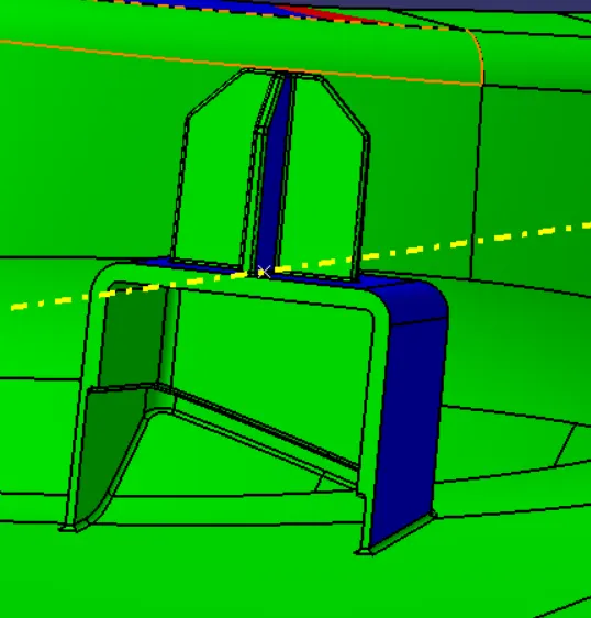
DESIGN RULES FOR DOG HOUSE:
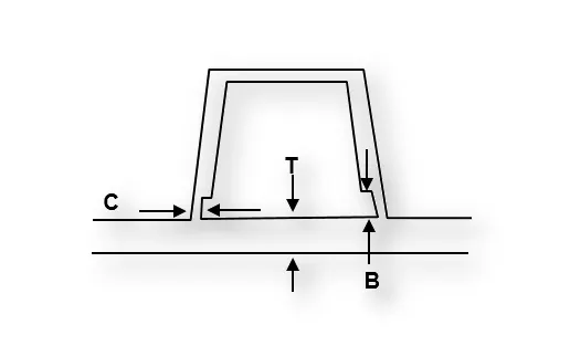
- Minimum height should not be Less than 6mm causes steel condition.
- 3:1 of steel width to height ratio. But 2:1 is preferred.
- Minimum width: 3:1 ratio of steel width to height. But 2:1 is preferred.
- Draft should be minimum 1.5degrees.
- Sink saver: height (C) = 40% of nominal thickness. Width (B) = 3.0mm-6.0mm.
- Optimal radius: 0.25mm
NOTE: The design rules for designing a 4-way locator pin are the same as that of ribs design rules.
Procedure:
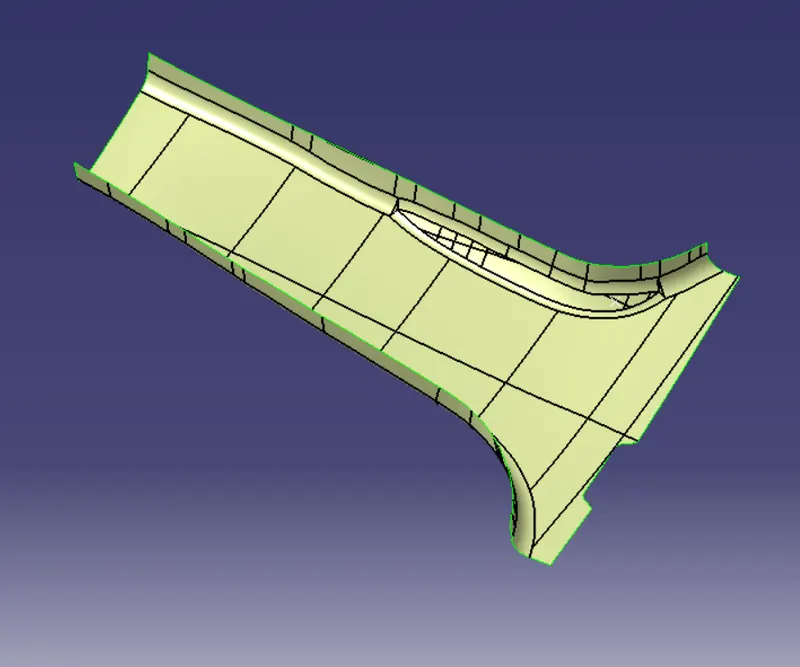
Input given:
CREATING TOOLING AXIS:
In this model, we need two tooling axis. One main tooling axis and the other side core tooling to clear the inside surfaces of the dog house. We have used bisecting line method to make the tooling axis. As the position of the tooling axis does not matter, we have taken the master section as the reference to make a point and a plane.
- First, bisect the two opposite lines of any master section using a positioned sketch.
- Then similarly, so for other master sections.
- Check if both are on the same line or not. If they are the same, we can name anyone as our tooling axis.
- If they are different then we will bisect them and the resulting line will be our tooling axis.
For making the lifter axis we make a simple line using point (earlier) and direction as parallel to the inside face.
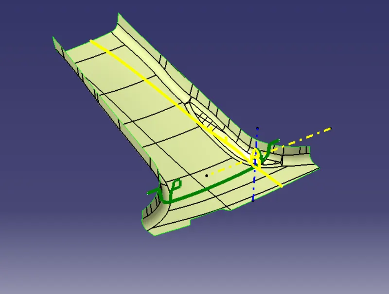
CREATING CLASS-B SURFACE
We extract the flat surfaces but due to the presence of many styling fillets on the class-A surface, we have extracted the whole class-A surface at once and offset it at 2mm ( thickness taken by measuring the master section). The resulting surface is our class-B surface.
NOTE: We should always extrapolate the surfaces as in the end we have to trim all surfaces together as they must intersect each other.
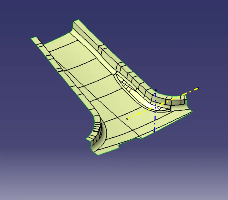
CREATING THE FLANGE:
When we observe the master section, we will find that class-A SURFACE has some projection outwards which is not in the given input. So we have to create these flanges on class-A on both sides, considering the master section as it contains the descriptions of the flange. Once we make the flanges on both sides of the surface, we can offset it and trim it with a class-B surface too. The approach below mentioned is followed to make the flanges:
- Extracting the respective boundary of class-A surface and then using smooth curve tool.
- Sweeping this curve with the reference surface as class-A surface (make sure it is extending on both sides of class-A, this will reduce our time of creating extrapolate later).
- We have to put different values for the draft till the flange matches the master section.
- Once this is done, we get our flange. Offset it by 2mm downwards for class B.
- Trim them with their respective surface.
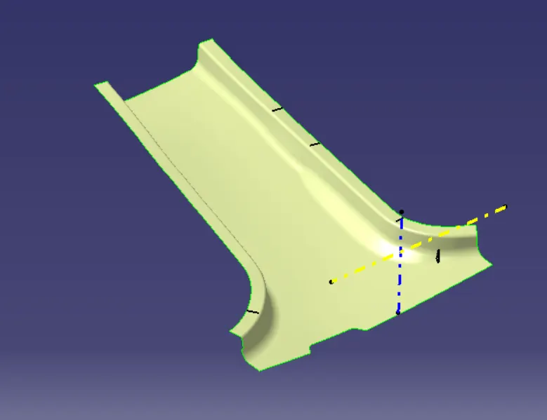
CREATING THE CLASS-C SURFACE:
In this model we have complex edges, it is difficult to make the sweep surface in one shot. So we have made the sweep surfaces only at the straight edges and followed various methods to make a C surface. At some edges, we extrapolated so they intersect each other and at some edges we made two straight surfaces and filled the gap between them, and then extrapolated them. Once this is done, we have to trim all of them with each other to get the class-C surface. We have extrapolated class-A with flange too so that it intersects with class-B and we get the required class-C surface after trimming it.
Once we have every surface to create a surface model we can follow the following steps:
- Trim class-A and class-C together.
- Trim the result with a class-B surface.
- Go to part design and close the model to get a solid model.
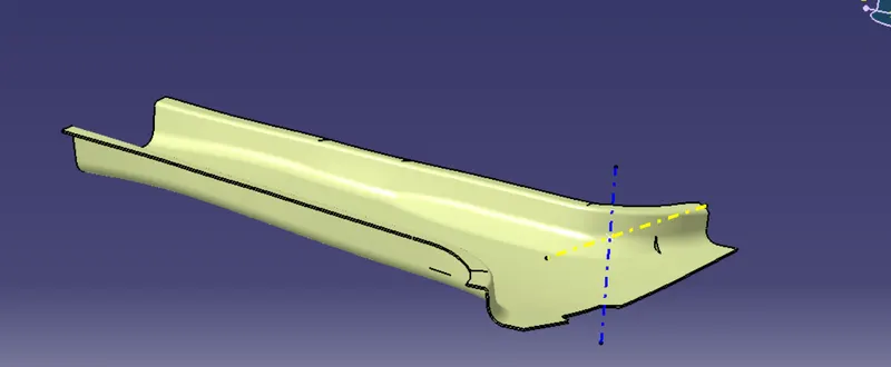
B-SIDE FEATURES:
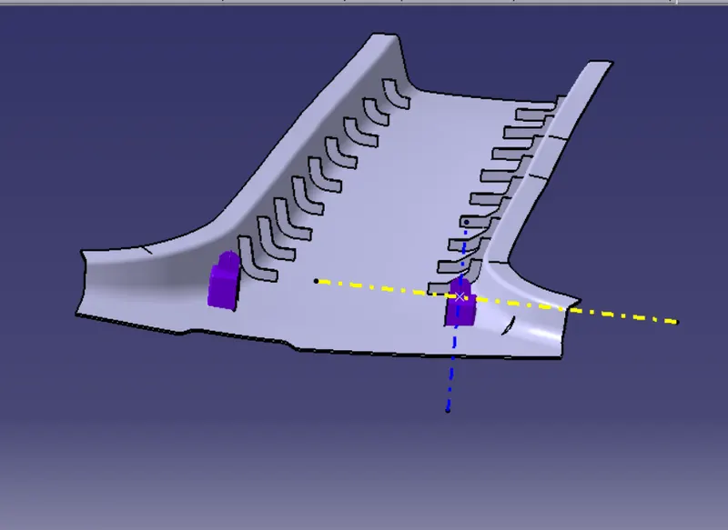
Once we get our solid model we can start working on B-side features. We will get the from the master section. On observing the master section we concluded that the features are a dog house, 4-way locator pin, and ribs.
The design rules mentioned above were followed for creation of these features.
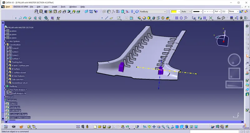
The final model after ceating these features is shown below:
Tree structures:
Various orientations:

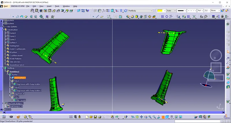
Draft Analysis:
CONCLUSION:
- Class A Surface was checked for any irregularities and if the surface is good then develop other surfaces. Class A was not clearing with the 3-degree draft in some areas and the same was shown in a PowerPoint presentation.
- Studied the Master section. The flanges were missing from class A and the same was created.
- Class B is created by offsetting the class A by 2mm(following master section).
- Class C was created by sweeping Class A with a draft of 3 degrees.
- All three surfaces were trimmed and a Close surface was developed.
- B-side features, Locators with Dog house were created.
- Ribs were created along the walls to add strength and to increase stiffness.
- Draft Analysis was done to check if all features are clearing the tooling axis.