Week 9 - Project - Master Section Development
REPORT ON B-PILLAR DRAFT ANALYSIS
Objective: The main purpose of the challenge was to create the Class-B surface, Class-C surface with the given Class-A surface of the B-pillar and performing the draft analysis by creating the tooling axis of the plastic component by taking the thickness of 2mm of the surface.
Tooling axis creation process
- The first step of the process is to check the continuity of the surface, which can be checked by the features or commands called join and boundary.
- Then we have to visually analyse the tooling axis of the surface, and create the dummy tooling axis of the component in the suitable direction.
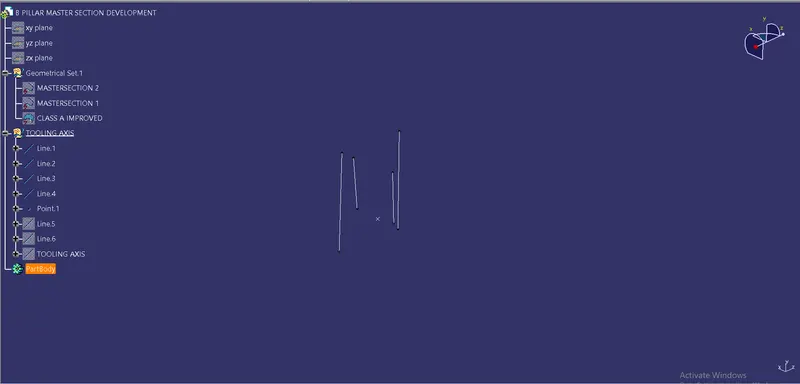
- Intersection of the surface is done on the axis which is suitable for the surface.
- Then the surface lines are created to check the intersection with the tooling axis.
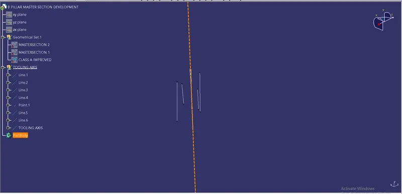
- Then we have to bisect the surface lines with the dummy tooling axis to form the final tooling axis.
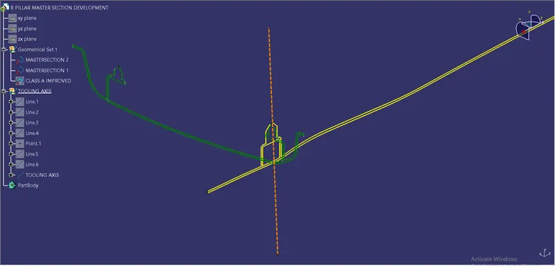
Bisecting Method
For Creating the tooling axis of the component the surface lines are intersect with the dummy tooling axis. The process of the bisection is explained below:
- The surafce lines of the surface which called boundary is extracted from the surface.
- The lines from the draft area is created which is parallel to the tooling axis by point to point method
- Those two draft surface lines are bisect with the dummy tooling axis.
- Then the final output of the bisecting lines is tooling axis of the component.
Draft Analysis
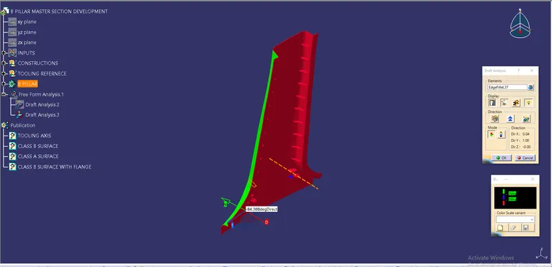
The purpose to perform the draft analysis on the component is to check the elgibility of the component in the maufacturing process of the plastic moulding. By performing draft analysis on the component we can check the draft angle of the component which generally is 3 degrees in plastic component, the draft angle helps to easily remove the component from the mould in the core and cavity in the manufacturing process.
The process to perform the draft analysis on the component is:
- First, Go to Insert>Feature>Insert feature draft analysis
- Then position the compass on the axis line we created.
- Then select the surface.
- Then use the Analyse under running point to check the draft angle of the surface.
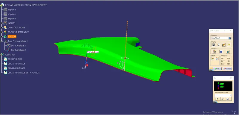
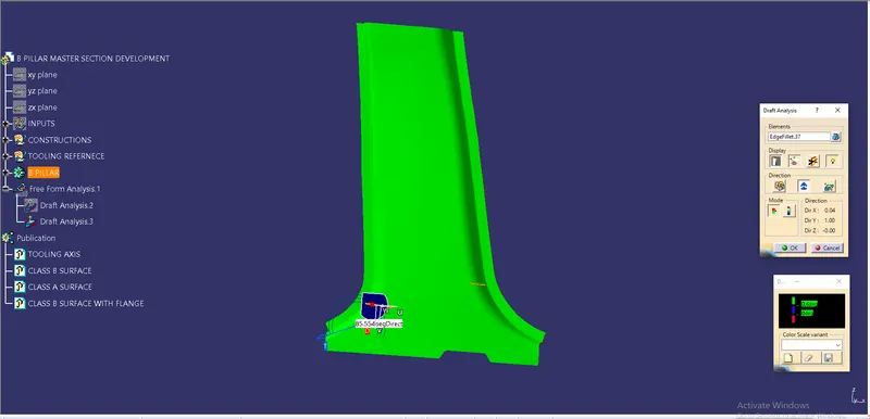
Draft Analysis on Class-A surface
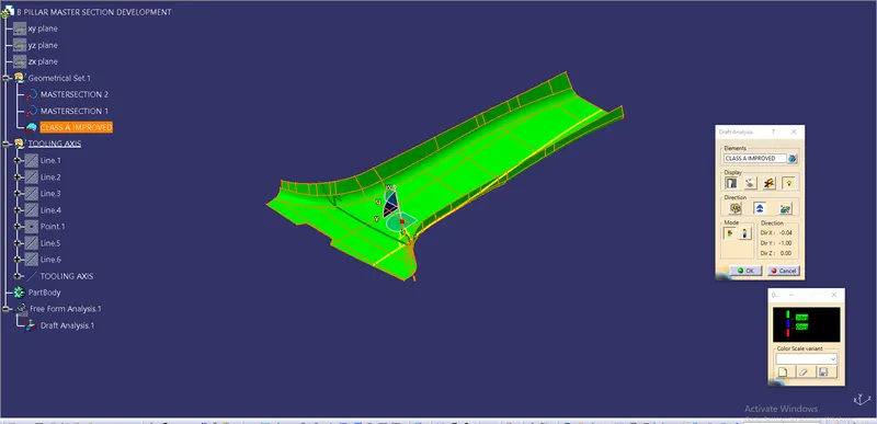
Final Draft Analysis
The draft was performed on the B-pillar was 3 degree draft.
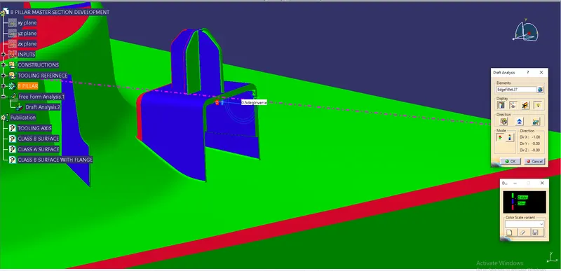
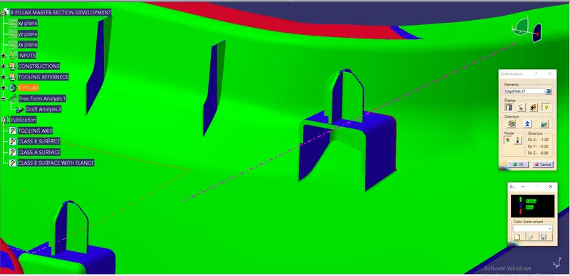
Draft Analysis of the Dog house
The draft Analysis performed on the Dog house and the Rib was the 0.5 degree draft.
Different Orientations
Front View
Side View
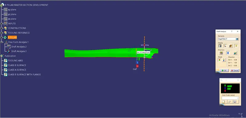
Top View
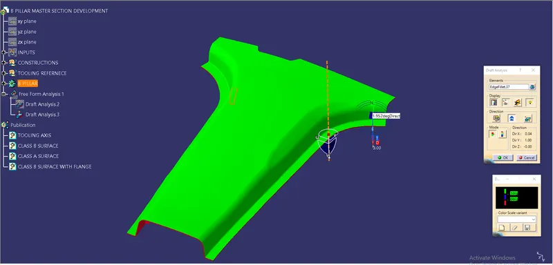
Isometric View
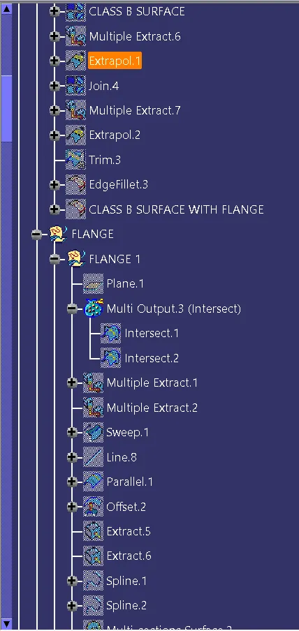
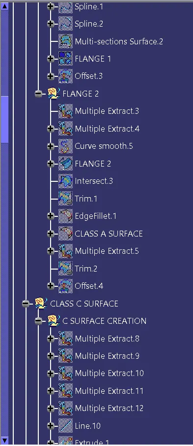
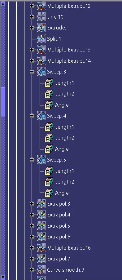
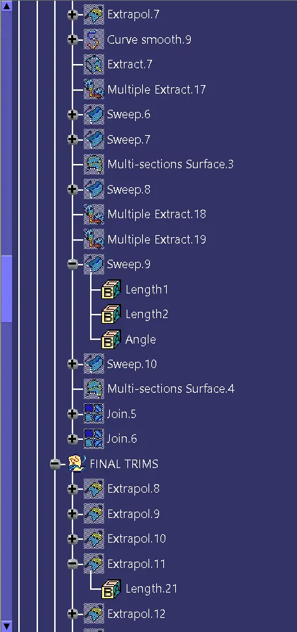
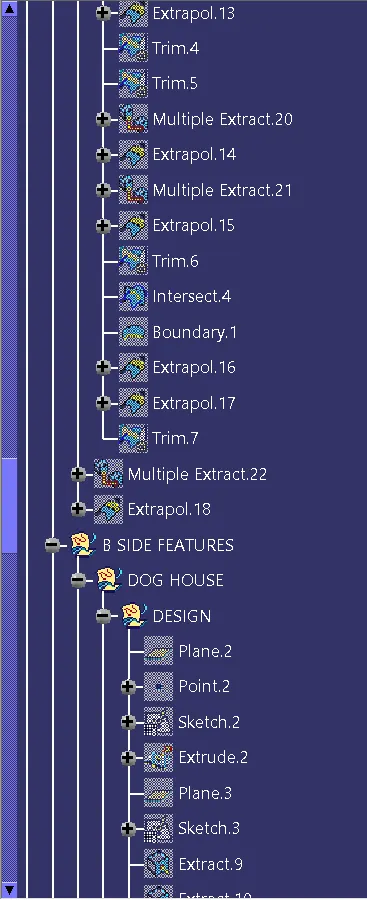
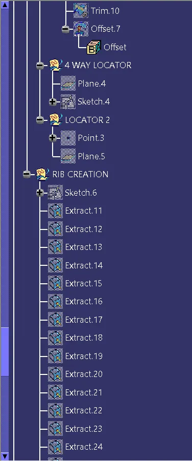
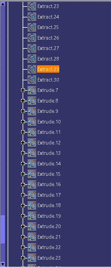
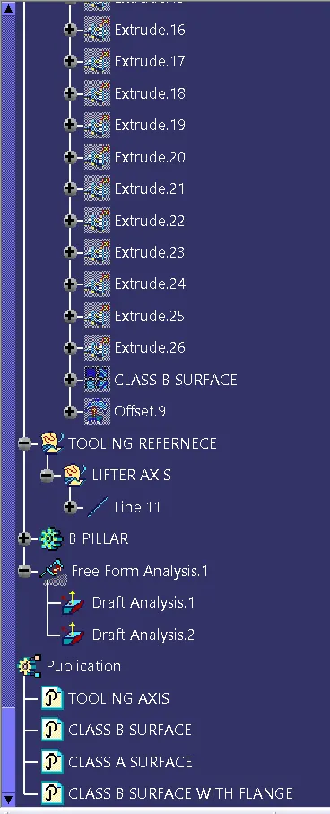
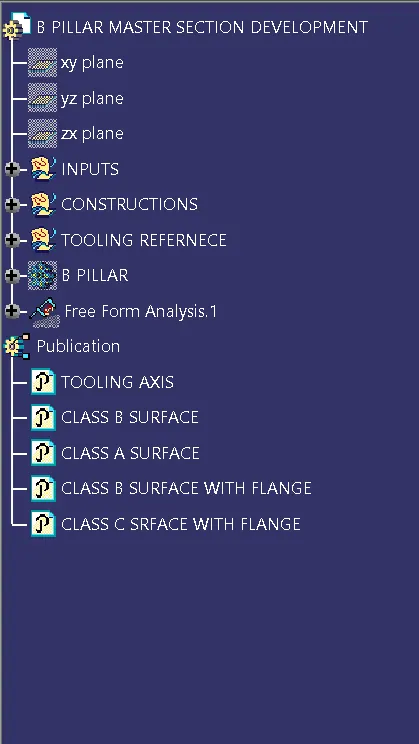
Design Tree
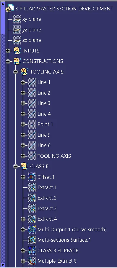
Publication
This feature is used to get the easy access of the component or feature present in the design tree.
Publication of Tooling axis, Class-A surface,Class-B surface with Flange, Class-C surface is done in the design tree.
Conclusion
The draft analysis was performed in Catia V5 to check the draft angle provided on the plastic component for easy removal of the part in the maufacturing process.