Week 9 - Project - Master Section Development
Aim: Create B-surface, C-surface, Screw boss, Dog houses, Flanges, Ribs to the given Class A master section and perform draft analysis to the given class-A surface.
Master section: Master sections are the guides for design requirements that decide the component packaging after technical (Styling, Concept, or Class-A) surfaces. They give reference to some of the features which are indicated in contours.
Steps to be followed:
- CLASS A
- Tooling axis and draft analysis
- B surface and C surface creation
- Closed body creation
- B side feature creation
- Side core axis
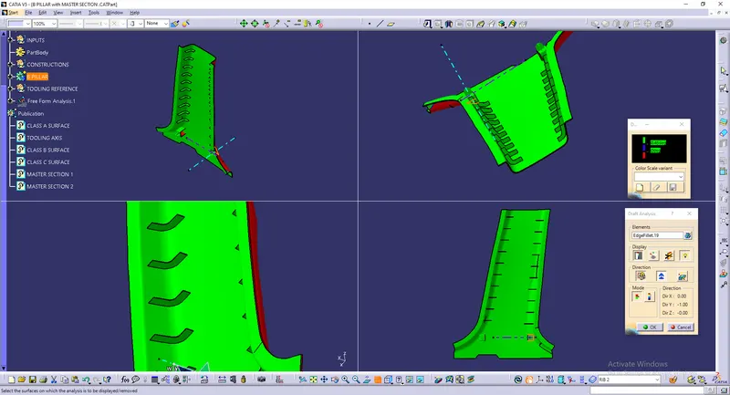
- Draft analysis
Procedure:
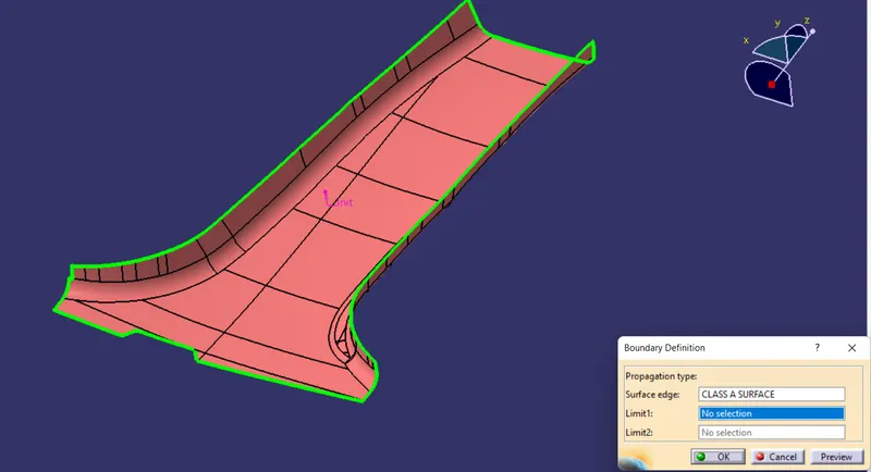
- Check the given Class-A surface by using the boundary tool whether any openings in the class-A surface.
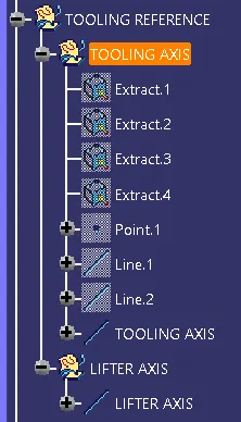
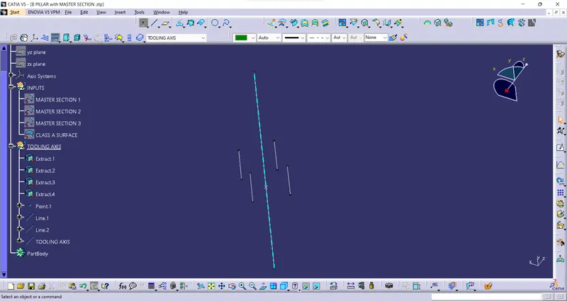
- Extract the edge lines of the locator which is mentioned in the master section. These lines are further used for the creation of the main tooling axis.
- Create the point by taking reference from the locator edges endpoints and selecting between the points and selecting the middle point and creating a point.
- From the point and the edge lines of the locators create a bisecting line and take it as the main tooling axis.
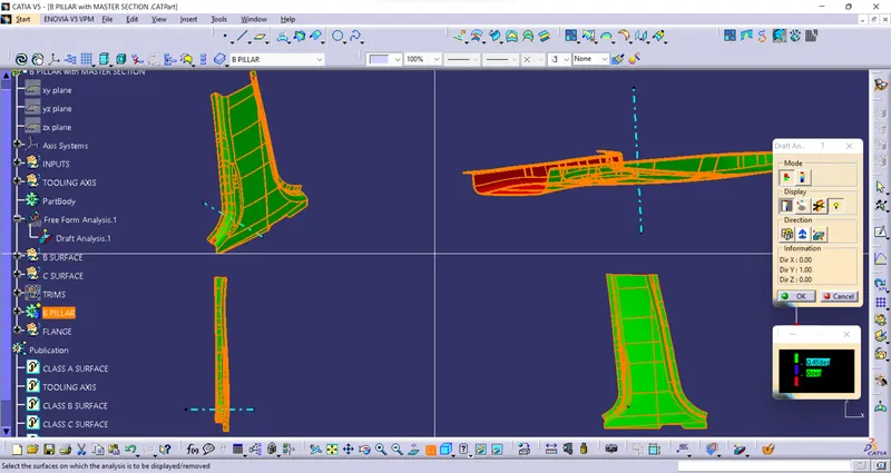
- Perform draft analysis to the class A surface by taking the main tooling axis as the draft direction.
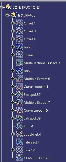
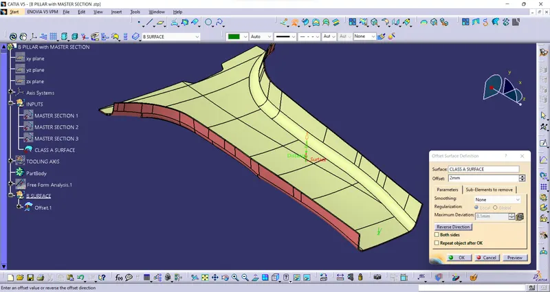
- Create a class B surface by offsetting the class A surface with 2mm, that offset is our class b surface.
- Create the plane through the master section by selecting the random three points on the master section.
- Intersect the plane with the class A surface to create the section contour of class A.
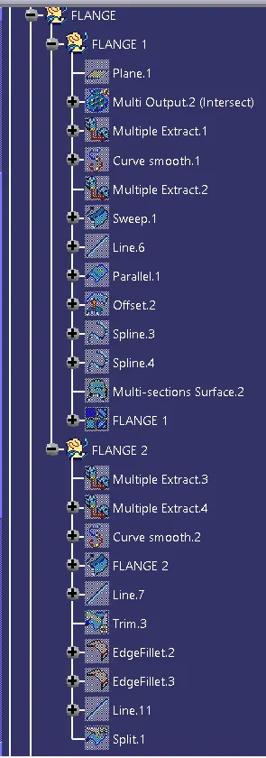
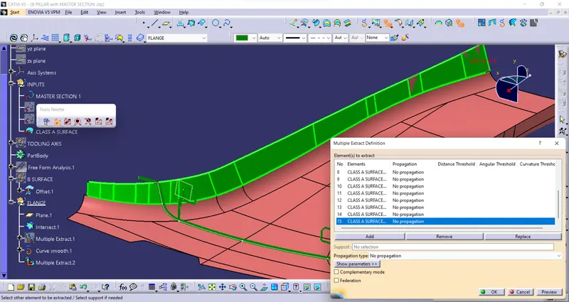
- Extract the edge of the class A surface and smoothen the curve which will be used for generating the flanges on both edges of the class A surface.
- Extract the supporting surfaces which help create the sweep surface concerning the extracted curve.
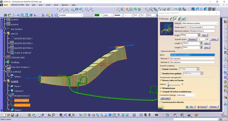
- Sweep the curve with the reference surface and adjust the angle to match the master section.
- Keep working on the sweep until it lies parallel with the master section by taking measurements between the generated flange and the edges of the master section.
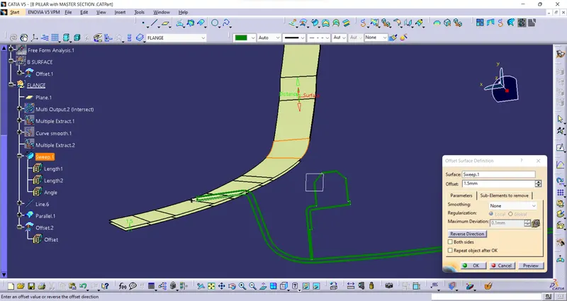
- Offset the flange and correct the errors with a multisection surface and join all the individuals.
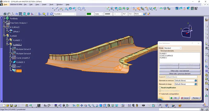
- Similarly, create the flange on another side and trim with the class A surface. Apply the fillet to the sharp edges between the flange and the class A.
- Edges creating errors while trimming the off-set flanges with B surface. Rectify them with the multisection surfaces. Trim the flanges with the class B surface
- Class A and Class B surfaces are shown in the below picture with an offset distance of 2 mm as measured from the master section.
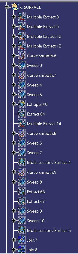
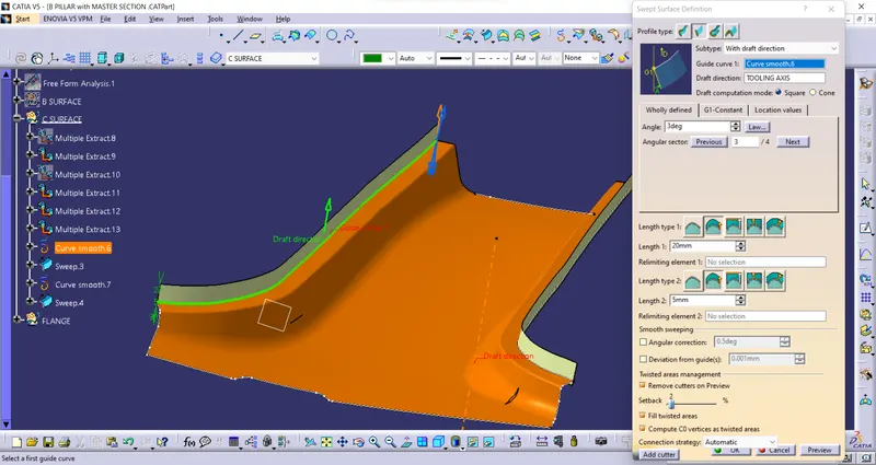
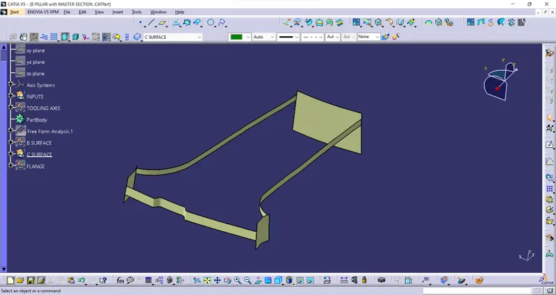
- Now create a class C surface by extracting the boundary of the class A surface and sweeping concerning draft direction using the sweep tool.
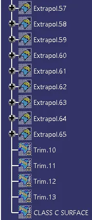
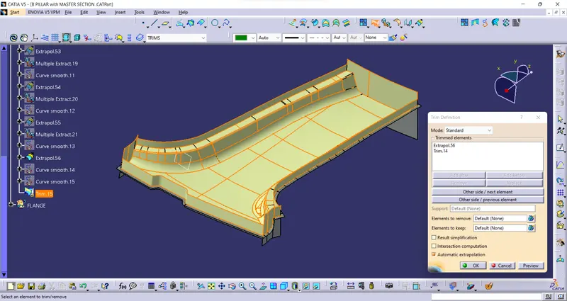
- Extrapolate the surfaces where they needed to join the surfaces, avoid the errors while trimming, and trim the class C with class A surface.
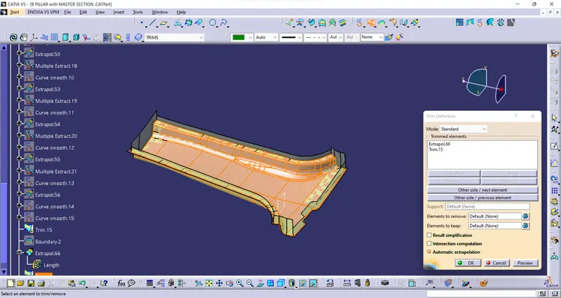
- Trim class B with the trimmed surfaces of class A and Class C. This is our final trim to create a closed body, check the closed body by using the boundary option whether any openings occurred while trimming.
- With the help of a close surface we create the final solid plastic part.
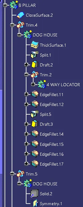
- Now work on the B side features such as Dog house, Screw boss, etc.,
- Create a plane on the master section at the mid-point of the master section.
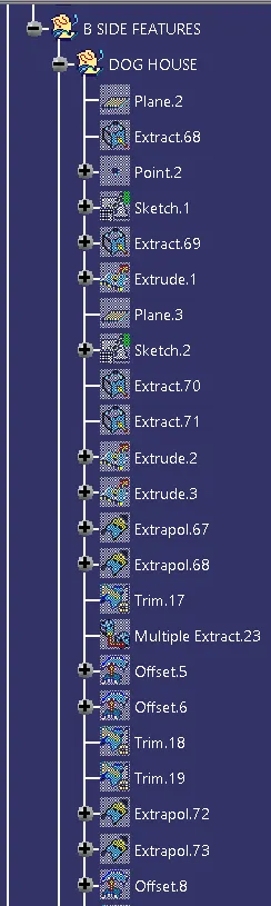
- Using positioned sketch concerning the plane and the point, project the edges of the master section, concerning the projected edges create the outline of the dog house, and constrain it.
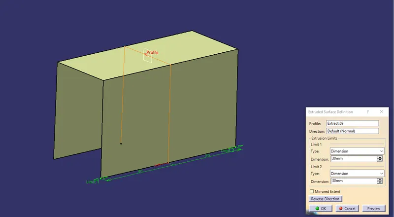
- Extract the inner side of the dog house and surface extrude it and repeat the same process to the other master section presented on the same plane.
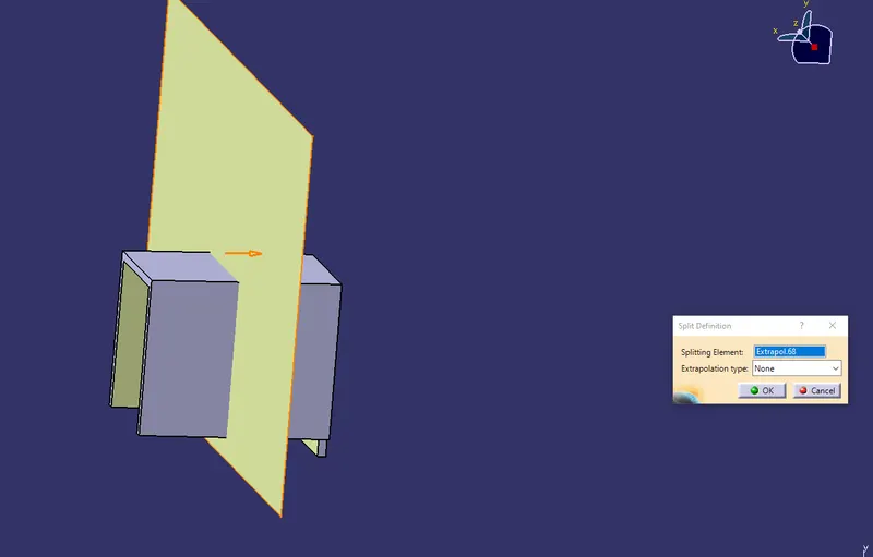
- Trim the unwanted surfaces of the extruded edges and thicken the trimmed surface to 2 mm, Then split the thickened surface with the front surface.
- We have to reduce the thickness of the dog house at the intersection point to avoid sink marks, Take B = 5 mm C = 0.4 x 2 = 0.8 mm
- First, split the dog house with the B surface and use the reference of the dog house sketch and create a profile and extrude. Split the extruded surface with the dog house.
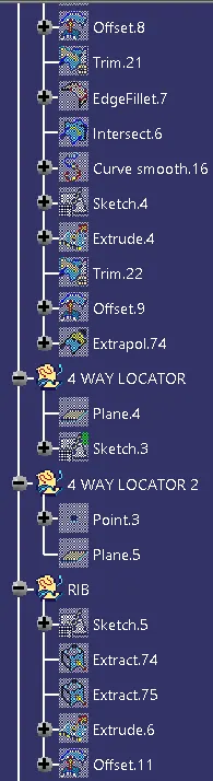
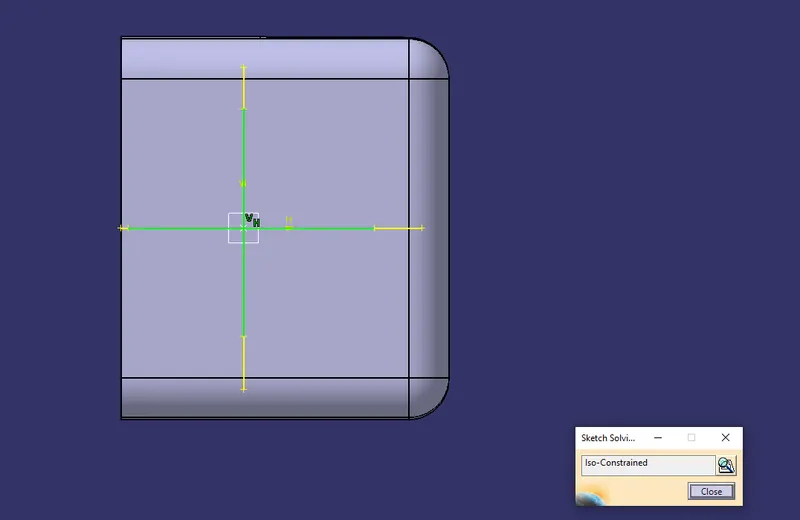
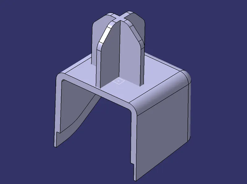
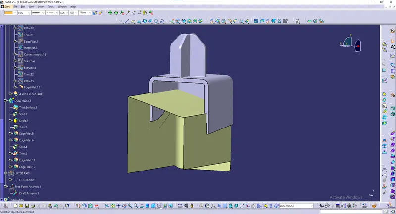
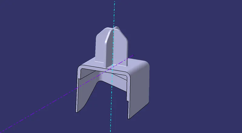
- Create the positioned sketch on the top of the dog house and take references from the master section sections. Create the lines for the 4-way locators.
- Thicken the created line using a pad tool with a thickness of 1.5 mm up to a height of 18 mm from the top of the dog house. Chamfer the edges of the 4-way locator by taking reference to the master sections.
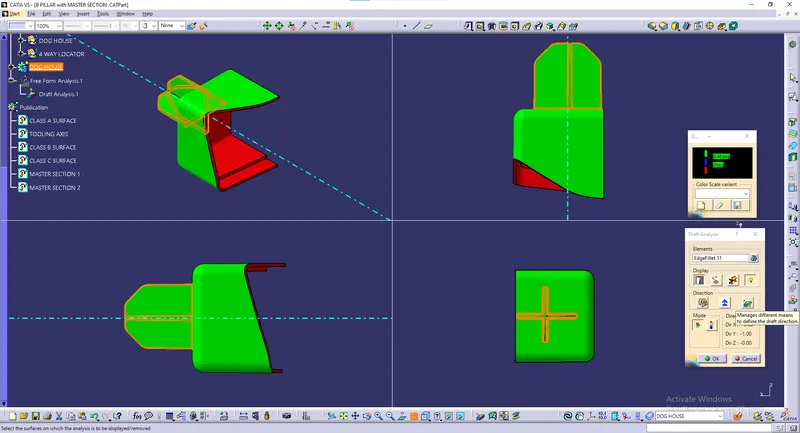
- Add to the dog house and apply fillets and the do draft analysis to the Dog house and the 4-way locator.
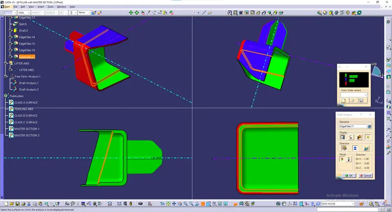
- Create a Lifter axis as a reference to the dog house, Apply a draft to the inner faces and create a draft analysis.
- Union trim the dog house with the B-pillar, Translate the Dog House by taking reference point and plane, and union trim with B-pillar.
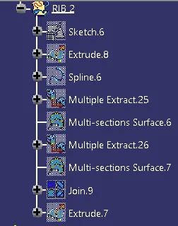
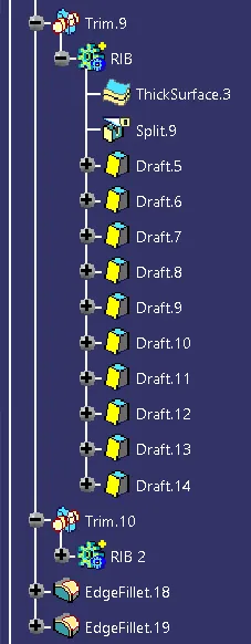
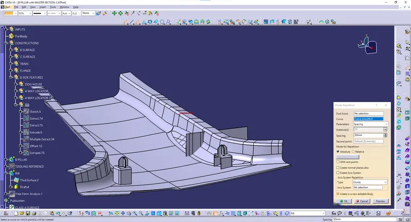
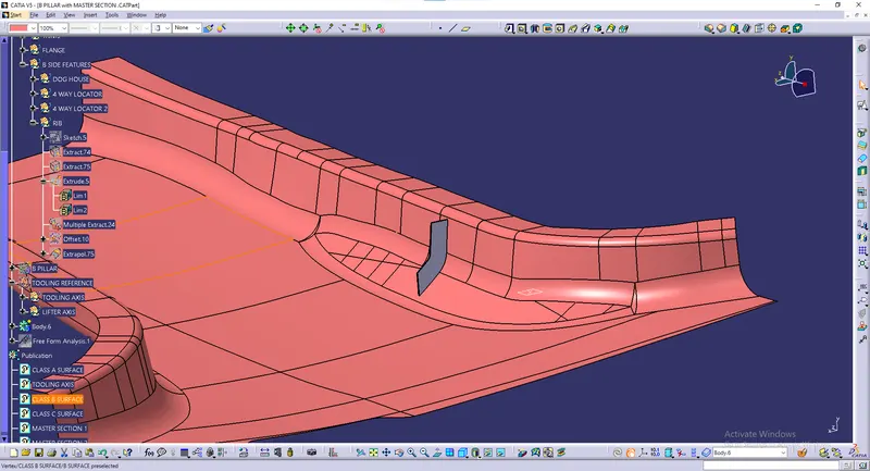
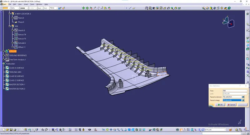
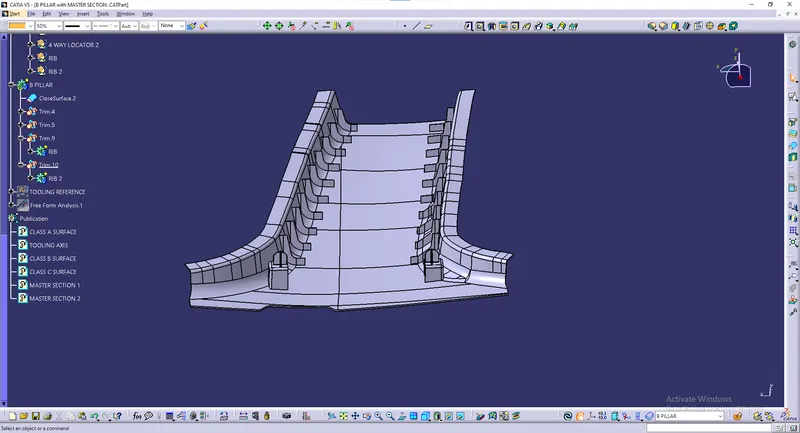
- Creating Rib using positioned sketch splitting surfaces, draft the faces, Later union trim the rib with the B-pillar.
- Take the reference curve from the B surface and create the equidistant points in it, Create the array of surfaces and split with the offset B surface, Union trim them with the B pillar.
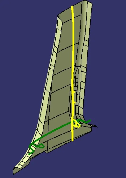
Class-A surface with multisection:
check class A:
Tooling axis:
Draft analysis:
Class B:
Flanges:
Class C:
Final trim:
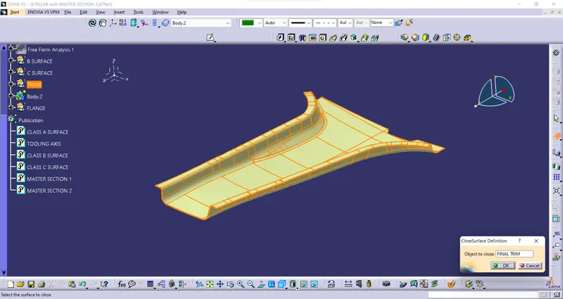
B side features:
Dog house:
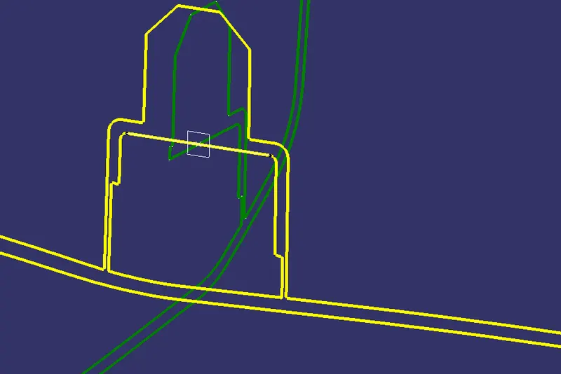
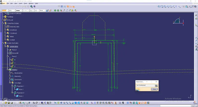
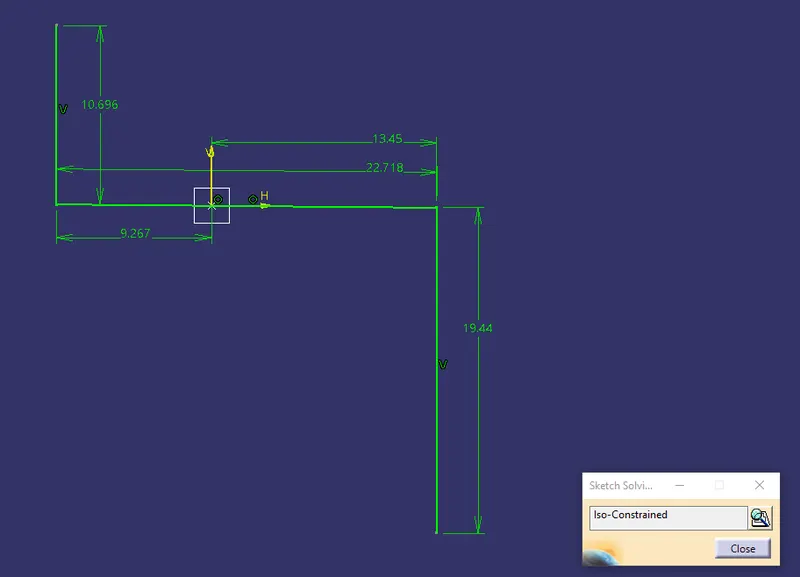
4-way locator:
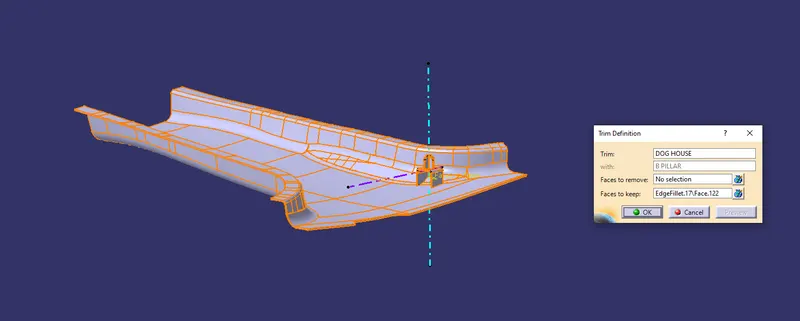
Dog house transverse to other side:
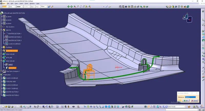
External draft analysis for the Dog house with 4-way locator:
Inner draft analysis for the Dog house:
Ribs:
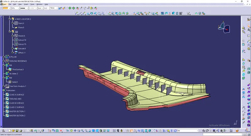
Final output:
Draft analysis :
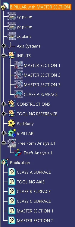
Tree: