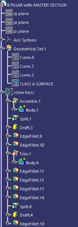
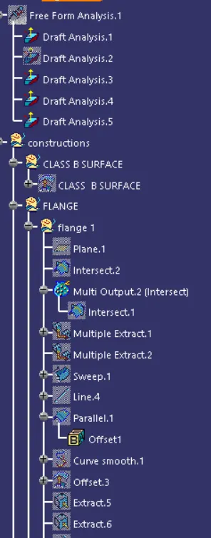
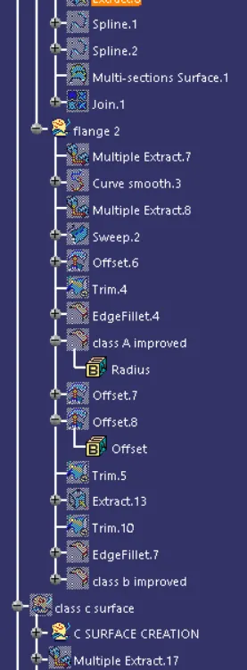
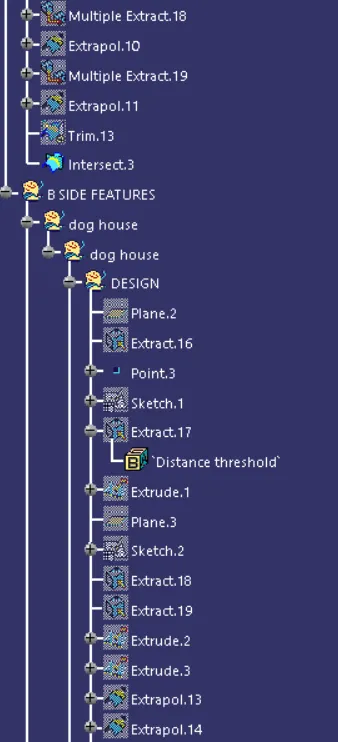
Week 9 - Project - Master Section Development
AIM: -
To design a B pillar with the given master section to follow the design criteria and thickness and thereby develop a closed volume part.
INTRODUCTION: -
The B – pillar is the post between the front and back seat doors of a car, connecting the roof to the body. It can also be defined as the vertical roof support structure located between the front and rear doors on a typical vehicle. It corresponds with the a pillar located on either side of the windshield at the front of the car and the C pillar which sits on either side of the rear window on a typical sedan car.
MASTER SECTION: -
Master section are the guides for design requirements which decide the component packaging after technical (Styling, concept or class-A) surfaces. Following is the general workflow that is followed for the design and development of interior and exterior automotive trims in OEMS.
PROCEDURE: -
After importing the model into Catia, check the given class A surface for geometry errors or if the faces are missing create a new face with the multi section tool available in Catia.
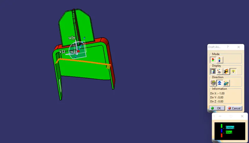
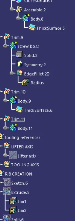
In order to provide the draft for the entire component, tooling axis has to be created for the core and cavity to be designed in the later stages.
From the given master section, create the tooling axis with the bisecting line option available in the line tool.
Next aim is to create the B-surface which has to be created 2mm from the class A surface, which has to be an exact replica of the Class -A surface provided. Also flanges has to be created on either ends of A surface as well as B surface with reference from the master section given.
The general steps followed in creating a surface is by extracting the surfaces without fillets, untrim and extrapolate the extracted class A surface if needed and offset the surface to the part thickness given. Next step is to trim or split the surfaces according to the shape needed.
After the B surface is generated, C surface has to be developed in the class A surface using the sweep toolbar without any generic changes in class A surface with minimum draft angle of 3 degree. All the draft angle has to be given outside of the part material has to be added rather than cutting it.
After the c surface is created all along the boundary of class A, join and trim it all together to make it as a single surface.
Now the class A surface and class C surface has to be trimmed to form as a single surface and thereafter trim it with the above developed class B surface in order to get the B pillar part.
After which the part is created, check for the boundary if it is closed or not and now change the workbench to part design and create a solid part out of it using the closed volume tool.
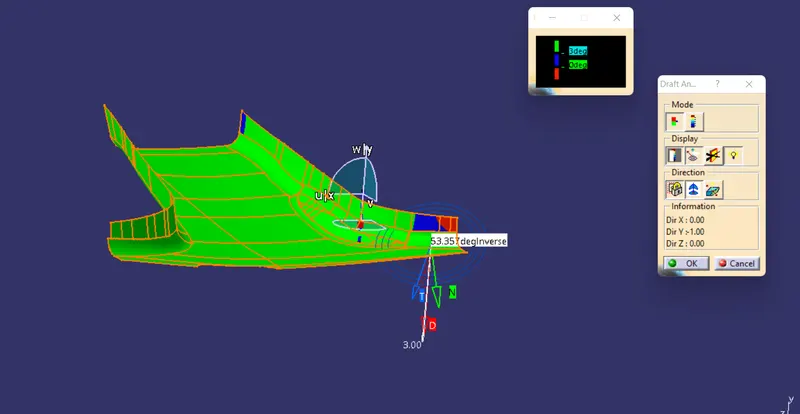
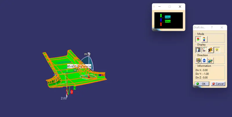
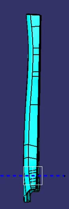
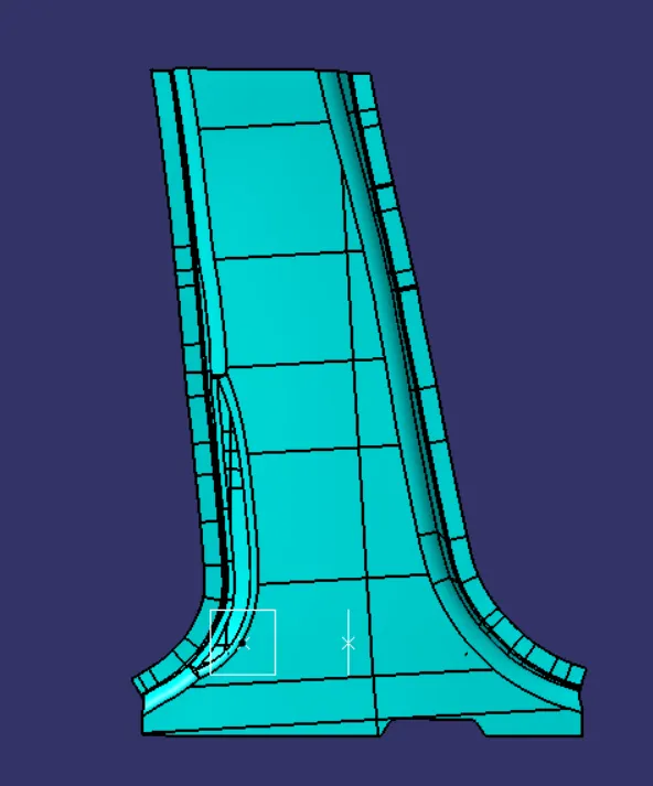
After the creation of closed body, check whether the main tooling is clearing all the part within the draft given. The draft analysis of the B pillar is given below.
DOG HOUSE WITH LOCATOR AND RIB CREATION: -
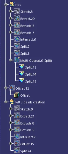
For the rib and dog house, proper design rules or criteria has to be followed.
Minimum height: - less than 6mm causes steel condition.
3:1 ratio of steel width to height. But 2:1 is preferred.
Minimum width: 3:1 ratio of steel width to height. But 2:1 is preferred.
Draft: 1.5 degree.
Indore to avoid sink marks: height (C) = 40% normal thickness. Width (B) = 3.0mm-6.0mm.
Optimal radius: 25mm.
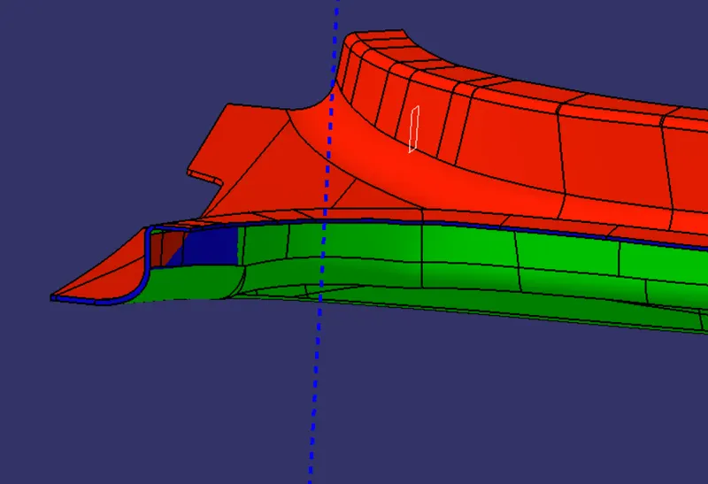
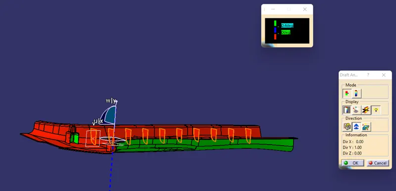
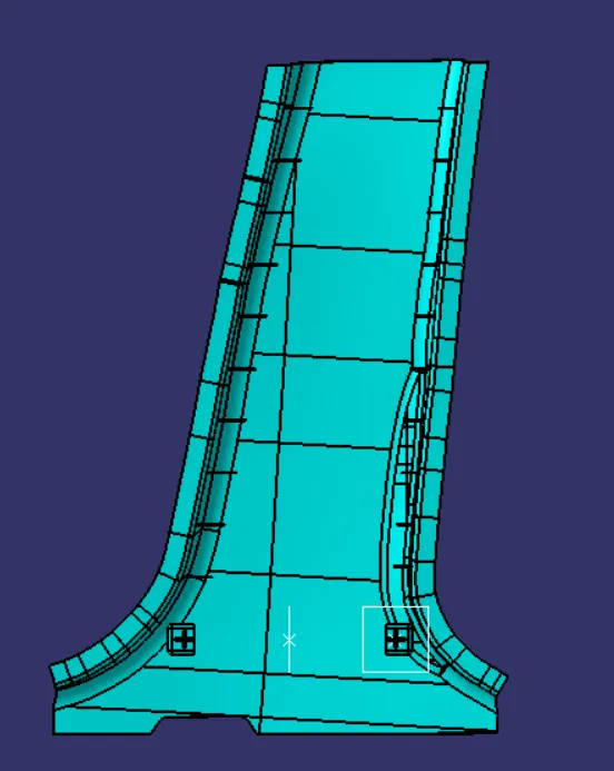
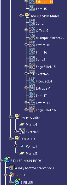
After developing the dog house, the inside part will not be drafted with the main tooling axis, so that a side core axis or lifter axis has to be created and separate draft has to be given to the interior of the dog house. The four-way locator can be easily developed with the reference from the sketch of master section and extrude with applying thickness to it. With applying proper chamfer, draft and fillet radius, locator can be created successfully.
The draft analysis for the dog house is given.
CONCLUSION: -
The B pillar has been developed from the given master sections given and b side features of dog house with locator and ribs has been created by following the design rules and criterias.