Photo Realistic Rendering
PHOTO REALISTIC RENDERING BY USING SOLIDWORKS
INTRODUCTION:
The report contains a detailed explanation of the design of an bike by using solid works from part modelling to final rendering of the assembly.
DESIGN METHODOLOGY:
SKETCHING
PART MODELING
ASSEMBLY
PHOTO-REALISTIC RENDERING
PARTS MODELED:
1.front fender
2.rear fender
3.transmission belt
4.chain
5.kick stand
6.oil tank
7.chassis
8.engine
9.gas tank
10.pedal
11.front fork
12.front wheel
13.rear wheel
Features used:
Boss extrude: This feature is used to expand the object in 3D according to sketch plane.
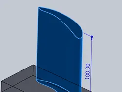
Extrude cut: Extrude cut feature used to cut/remove the 3D object in linear path according to sketch.
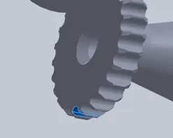
Fillet: Fillet is a feature used for making round internal or external edges to avoid sharp edges and make it smooth.
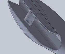
Lofted boss/base: Lofted boss is a feature used to achieve complex shapes. It does this by interpolating surface between various cross-section of a model. These cross-sections can be sketches, faces, or edges.
Split: Split tool is used to split single solid part into two solid parts. It is used to project an entity onto other surface or curved/planer faces.
Dome: Dome is a feature used to make dome shaped extrude including elliptical dome.
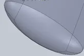
Shell: Shell feature used to make dome shaped extrude including elliptical dome.
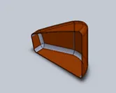
Combine: Combine tool is used to make integration of two solid parts which intersect each other as same solid part.
Chamfer: Chamfer is used to make integration of two solid parts which intersect each other as same solid part.
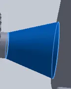
Linear pattern: The linear pattern is used to create a different number of instances required to create the pattern linearly.
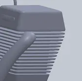
Curve driven pattern: Curve driven pattern is a feature used to make any pattern which followed by the curve is sketched before.
Circular pattern: Circular pattern is a feature used to make 3D feature into circular pattern according to number of instances.
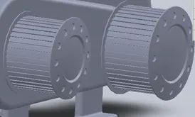
Revolve boss base: Revolve feature is used to make cylindrical or circular 3D extrude along with a given reference axis as per drawn sketch.
Revolve cut: Revolve cut is used to cut or reduced the extrude of cylindrical round surface.
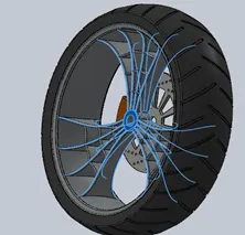
Move/copy body: This feature is used to move or copy the 3D body to one place to another place.
Mirror: Mirror is used to mirror feature or body by reference of the selected plane.

Sweep: This feature is used to sweep any kind of fully defined sketch along with the plane.
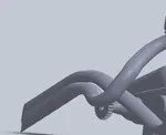
Sweep cut: Sweep cut is same as sweep feature but its directly proportional to sweep which makes a cut along with the sweep path.
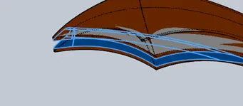
Swept Surface: It is used to make a surface along with a path the curve is driven.
Boundary Surface: Boundary surface is used to make a surface in between two finished surfaces.
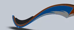
Loft surface: Loft surface is used to make loft in between two profiles along with guide path.
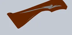
Knit surface: Knit surface is used to knit the two free edges or open edges of the surfaces together also it reduces the gap between the two edges of the surface.
Surface trim: Primarily used to cut away material from a surface, and provides two modes standard and manual.
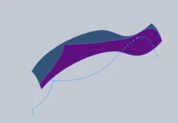
Projection curve: Projection curve is a 3D curve which is projected on the basis of two different 2D curves in two different planes.
Blocks: Edit & insert blocks from the drawing items and sketch entities that you use the drawing items and sketch entities that you use often such as standard notes. Title blocks, label positions and so on you can attach blocks to geometry or to drawing views.
Trim entities: It is used to trim the unwanted lines or extended entities in the sketch.
Appearances: An appearance define visual properties of the model including color and texture. Appearance do not affect physical properties which are defined by materials. Every material is a assigned a default appearance.
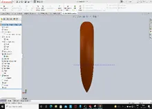
1.Front fender:
Front fender is placed above the front wheel to prevent debris and other materials from the road and the wheel from hitting the ride or other parts of the chopper.
Features used:
1.Sketch
2.Offset entities: In an open sketch, select one or more sketch entities, a model face, or a model edge.
3.Trim entities: use power trim to trim multiple, sketches entities by dragging the pointer across each sketch entity.
4.Revolved boss: Revolve feature is used to make cylindrical or circular 3D extrude along with a given reference axis as per drawn sketch.
5.Dynamic mirror: select a line or a model edge in an open sketch.
6.Split: Split tool is used to separate to single object to one or more objects.
7.Appearance: define the visual properties of the model.
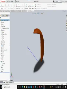
2.Rear fender:
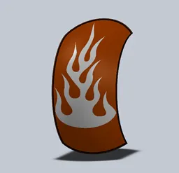
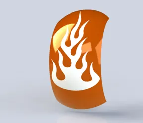
Similar to the front fender, the rear fender above the rear wheel protects the rider and the chopper from debris from the wheels.
Features used:
1.Sketch
2.offset
3.Trim entities: use power trim to trim multiple, sketches entities by dragging the pointer across each sketch entity.
4.Split: Split tool is used to separate to single object to one or more objects.
5.Appearance: define the visual properties of the model.
6.Decals: Adds decals and other such design to the parts.
3.Transmission belt:
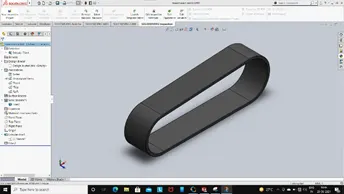
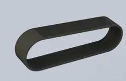
The belt is a loop of flexible material used to link two or more rotating shafts mechanically, most often parallel. Belts may be used as a source of motion, to transmit power efficiently or to track relative movement.
Features used:
1.Sketch: Two dimensional drawings of the model to be created with respect to a plane of view.
2.Offset: Creates an offset sketch at a specified distance.
3.Extrude boss: Add material to the part model. To create an extrude boss.
4.Fillet: It creates or changes the sharp edges to rounded shapes.
5.Appearance: Define the visual properties of the model.
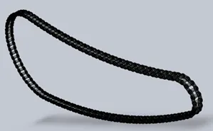
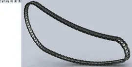
- Chain:
A chain is that transfers power from engine to rear wheel (drive wheel) of a bike, thus propelling it. Most of the chains are made up of plain carbon steel.
Features used:
1.Sketch
2.Trim entities
3.Fillet: It creates or changes the sharp edges to rounded shapes.
4.Block: Sketch entities can be saved as blocks so that they can be reused easily multiple times in other sketches.
5.Extruded boss : add some material.
6.Pattern: Parts can be repeatedly constructed as arrays along linear or curved sketches. It can be linear, circular or curve driven.
7.Appearance.
5.Kick stand:
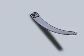
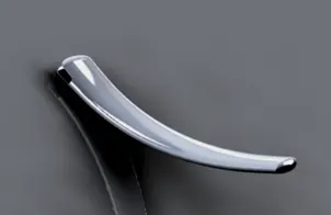
A kick stand is a device on a bicycle or motorcycle that allows the bike to be kept upright without leaning against another object or the aid of a person. A kick stand is usually a piece of metal that flips down from the frame and makes contact with the ground.
Features used:
1.Sketch
2.Lofted boss: Lofted boss is a feature used to achieve complex shapes. Which basically extruded loft surface by means of two lofted profiles along with guided curves direct the path of lofting.
3.Dome
4.Extrude: used to expand the object in 3D according to sketch plane.
5.Fillet: fillet is a feature for making round edges to avoid sharp edges.
6.Split: Split tool is used to split the single solid part into two solid parts.
7.Appearance.
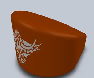
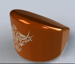
- Oil tank:
An oil terminal is an industrial facility for the storage of oil, petroleum and petrochemical products, and form which these products are transported to end users or other storage facilities.
Features used:
1.Sketch
2.Extrude cut
3.Combine: Used to combine multiple bodies to from s single body.
4.Fillet
5.Shell: Used to create a hollow material out of a solid part with a specified.
6.Appearance
7.Decal.
7.Chassis:
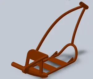
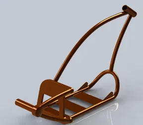
A chassis is the physical frame or structure of an automobile, an airplane, a desktop computer, or other multi-component device. Case is very similar in meaning, but tends to connote the protective aspect of the frame rather than its structure.
Feature used:
1.Sketch
2.Offset entities: In an open sketches one or more sketches entities, a model face, or edge.
3.Convert entities: In open sketch, click a model edge, loop, face, curve, external sketch counter, set of edges, or set of curves. You can also click an entity after clicking the convert entities.
4.Project curve: The project curve feature is more like the split line that the wrap feature. It wraps feature, it can do everything the split line feature with one exception, it gives up the ability to split faces in favor of being able to use open contour sketches that are within the boundary of a face.
5.Trim entities:
6.plane
7.Sweep: Create the path for the profile to follow. Use a sketch, existing model edges, or curves.
8.Split: Like the wrap feature, the split line feature will divide an existing face by the specified sketch. While the feature can work with open contours, it must use a sketch that fully encompasses the boundary of the face.
9.Revolved boss
10.Cut extrude
11.Fillet: fillet is a feature for making round edges to avoid sharp edges.
12.Combine: Used to combine multiple bodies to from s single body.
13.chamfer
14.Appearance
8.Engine:
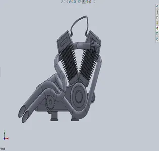
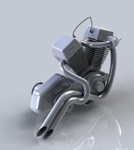
An engine is some machine that converts energy from to some mechanical energy, creating motion in the process. Engines – such as the ones used to run vehicles can run on a variety of different fuels, most notably gasoline and diesel in the case of vehicles. However, there do exist some alternative fuel types such as biofuels and natural gas. In thermodynamic terms, engines are generally referred to as heat engines, which produce macroscopic motion from heat. the heat in this case comes from the combustion of fuel in the engine, which moves piston.
Features used:
1.Sketch
2.Trim
3.Revolved boss
4.convert entities: In open sketch, click a model edge, loop, face, curve, external sketch counter, set of edges, or set of curves. You can also click an entity after clicking the convert entities
5.Extrude boss
6.Extrude cut
7.Offset entities: In an open sketches one or more sketches entities, a model face, or edge.
8.Dome
9.Fillet
10.Mirror
11.Circular pattern: circular pattern in solid works. To do that, click on the origin of the small circle, hold down the ctrl key, and select the origin of our boss.
12.Project curve
13.Composite curve: create composite curves by combining curves, sketch geometry, and model edges into a single curve.
14.Sweep: Create the path for the profile to follow. Use a sketch, existing model edges, or curves.
15.Appearance.
Gas tank:
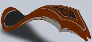
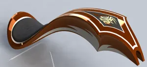
A fuel tank (also called a petrol tank or gas tank) is a safe container for flammable fluids. Though any storage tank for fuel may be so called, the term is typically applied to part of an engine system in which the fuel is stored and propelled (fuel pump) or released (pressurized gas) into an engine.
Features used:
1.Sketch
2.Trim Entities: : use power trim to trim multiple, sketches entities by dragging the pointer across each sketch entity.
3.Project curve: The project curve feature is more like the split line that the wrap feature. It wraps feature, it can do everything the split line feature with one exception, it gives up the ability to split faces in favor of being able to use open contour sketches that are within the boundary of a face.
4.Convert entities
5.Surface sweep: Create planes for sketching the sweep profile, sweep path, and if necessary, the guide curves.
6.Loft surface: The loft feature is an important tool for (surface) modelling in SolidWorks. The loft feature creates a shape by making transitions between multiple profiles and guide curves.
7.Surface knit: Select Gap Control to view edge pairs that might introduce gap problems, and to view or edit the knitting tolerance or gap range
9.Swept cut
10.Fillet
11.Appearance
12.Decal.
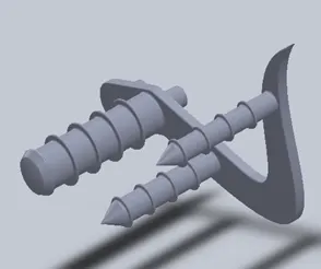
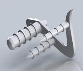
Pedal:
Pedal is used to support the legs of the rider.
Features used:
1.Sketch
2.Extrude boss
3.Fillet
4.linear pattern
5.Dome
6.Chamfer: A chamfer is an angled slope that’s added along edges to make them less sharp.
7.Appearance.
Front fork:
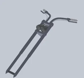
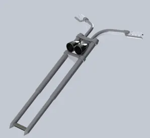
Most forks incorporate the front suspension and front brake, and allow the front wheel to rotate about the steering axis so that the bike may be steered. Most handlebars attach to the top clamp in various ways, while clip-on handlebars clamp to the fork tubes, either just above or just below the upper triple clamp. The fork and its attachment points on the frame establish the critical geometric parameters of rake and trail, which play a major role in defending how a motorcycle handles and dives during braking.
Features used:
1.Sketch
2.Extrude boss
3.Trim
4.Revolved boss
5.Split
6.plane
7.Convert entities: convers projection of edges and points on to a sketch.
8.Dome
9.Mirror: Mirrors the selected parts across a specified plane.
10.Combine
11.Project curve: Creates a 3D curve which is projected on the basis of two 2D curves.
12.Sweep: Creates a 3D curve Which is projected on the basis of two 2D curves.
13.Appearance.
Front wheel:
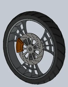
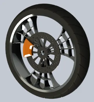
Front wheel drive reduces weight, decreases production costs, and improves fuel economy compared to a rear-wheel-drive system. It also improves traction since the weight of the engine and transmission is directly over the driven wheel.
Features used:
1.Sketch
2.Revolved boss
3.Trim entities
4.Fillet
5.Extrude boss
6.Revolved cut
7.Circular pattern
8.Chamfer
- Appearance.
Rear wheel:
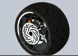
Rear wheel drive is used exclusively in all categories of motorsport where it’s allowed. It’s considered the driver’s performance as a trained and experienced driver can utilize the power being put down by the rear wheels to help steer the car through turns.
Features used:
1.Sketch
2.Revolved boss
3.Trim entities
4.Fillet
5.Extrude boss
6.Revolved cut
7.Circular pattern
8.Chamfer
9.Appearance.

ASSEMBLY:
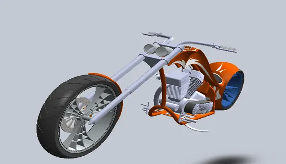
Part modeled are assembled with respect to each other and fixed. Chassis is the first part to be added. Every other part is fixed with respect to chassis.
MATES:
Mates’ features are used to create geometric relationship between parts to fix their position and motion with respect to each other.
RENDERING:
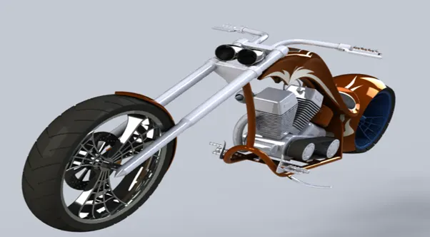
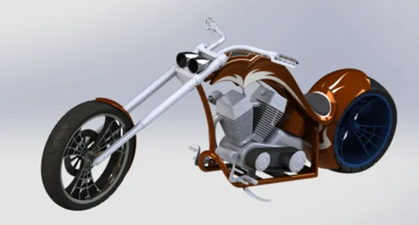
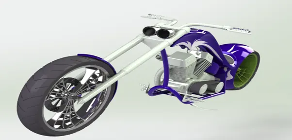
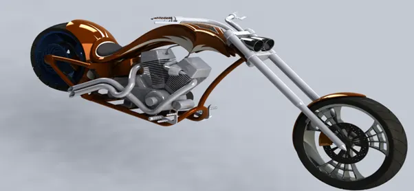
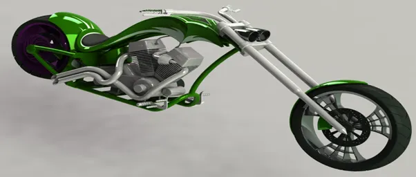
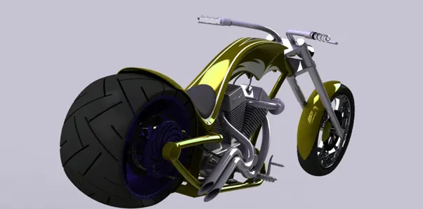
Rendering is the process in which photo-realistic images are created for the model designed. The environment can be set up according to the needs. Background images, camera directions, environment settings, lighting and shadows etc can be tweaked to create the best images possible.
In solid works rendering can be done using photo view 360 and solid works visualize.
CONCLUSION:
1.Parts of an American chopper are designed and modeled using.
2.Assembled the parts modeled using.
3.Photo-realistic rendering created using solid works photo view 360,and solid works visualize.