Radar Mast & Final Assembly of Yacht
Radar Mast & Final Assembly of Yacht
INTRODUCTION OF YACHT
The term, yacht, originates from the Dutch word jacht (pl. jachten, which means "hunt"), and originally referred to light, fast sailing vessels that the Dutch Republic navy used to pursue pirates and other transgressors around and into the shallow waters of the Low Countries.
The history of pleasure boats begins with rowed craft in Pharaonic Egyptian times, and other vessels in the waters of Burma, India, Mindanao and Japan. It described 8th-century Anglo-Saxon royal pleg-scips (play ships) that featured ornamented bows and sterns and which had the capability of cooking on board.
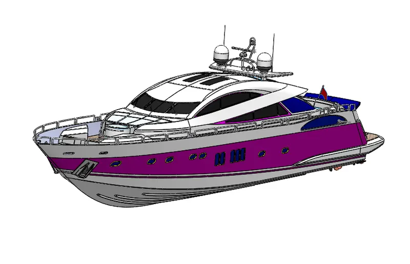
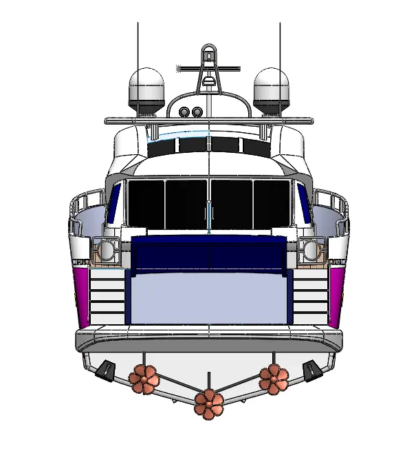
Different components of the yacht we deal by us:
1.Propeller
2.Rader
3.Hull
4.Garage door
5.Front seat
6.Middle seat
7.Rear seat
8.superstructure
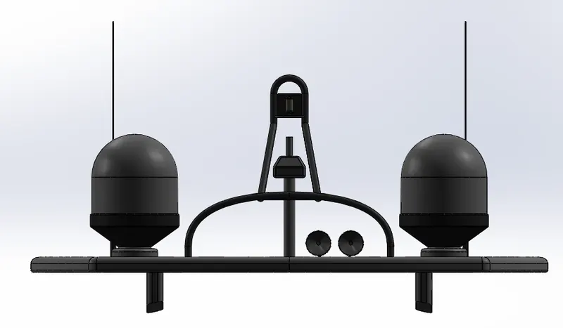
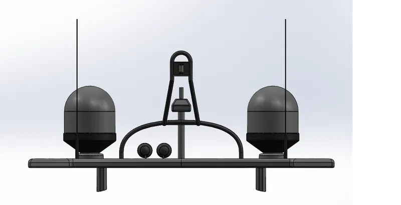
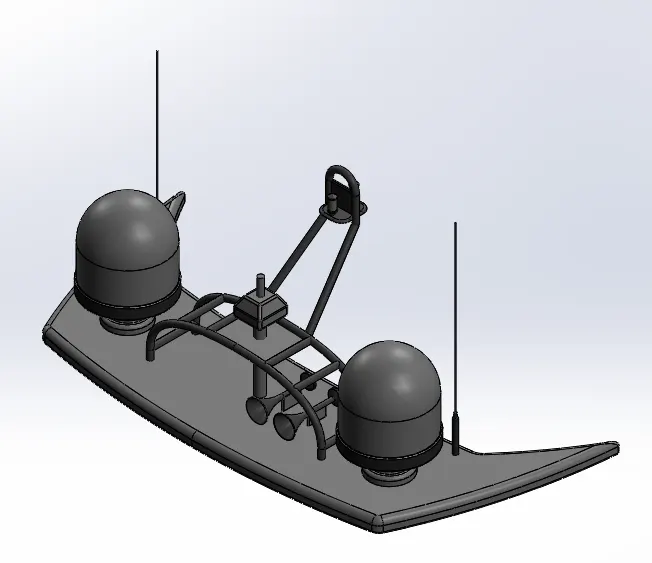
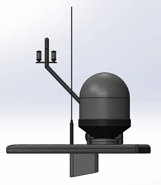
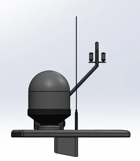
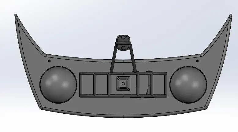
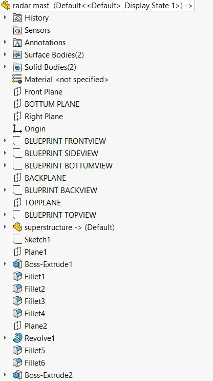
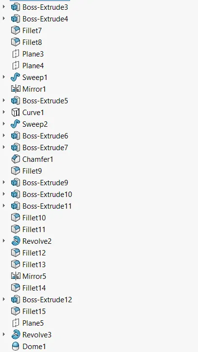
9.Radarmast.
DESIGN METHODOLOGY:
BLUE PRINT SETUP
SKETCHING
PARtS MODELING
ASSEMBLY
PHOTO-REALISTIC RENDERING.
FEATURE USED:
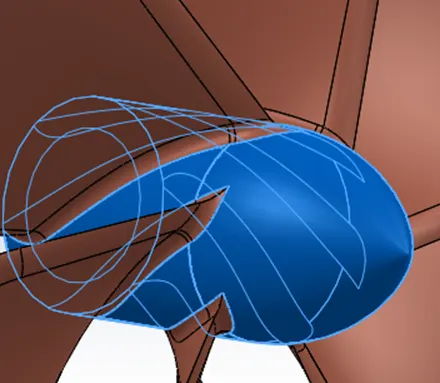
Revolve:
To create a sketch that contains one or more profile and a center line or edge to use the axis around which the feature revolves. Click one of the following revolve tools.
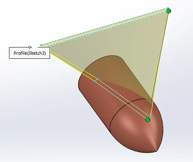
Loft:
The loft feature in solidworks allows you generate complex geometry in a single feature. It does this by interpolating surfaces between various cross-sections of a model. These cross-sections can be sketches, faces, or edges. In the loft interface, these cross-sections are considered “loft profile”.
Fillet:
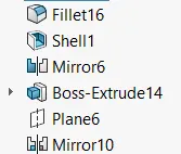
Fillet is a feature used for making round internal or external edges to avoid sharp edges and make it smooth.
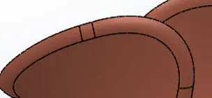
Extrude Cut:
Extrude cut feature used to cut/remove the 3D object in linear path according to sketch.
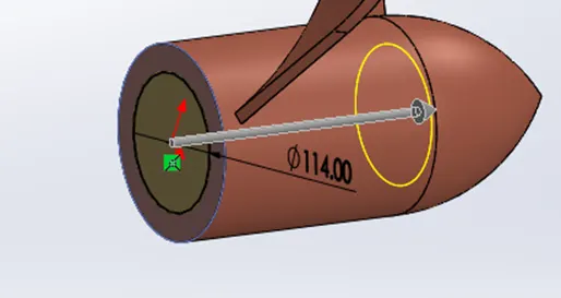
Circular pattern:
Use circular pattern to create multiple instances of one or more features that you can space uniformly around an axis.
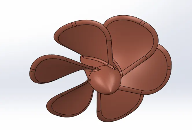
Boss Extrude:
This feature is used to expand the object in 3D according to sketch plane.
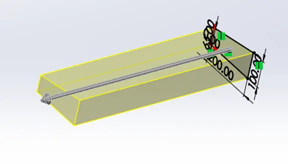
Mirror:
Mirror is used to mirror feature or body by reference of the selected plane.
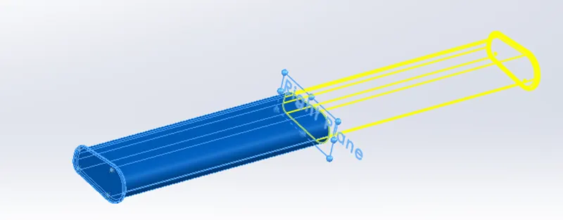
To build a sketch driven pattern:
Open a Sketch on the face of a part to create a seed feature on the model.
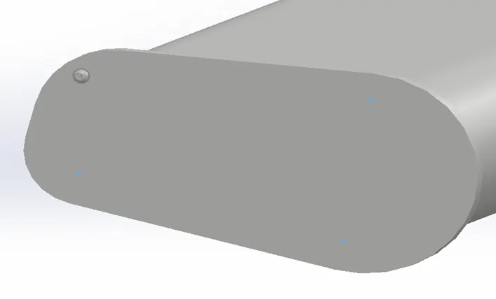
Split line:
Using the split line feature, the sketch lines are projected onto the selected faces, and divide the faces into multiple regions as defined by the sketch. Once the split line as created, these selected regions can have a different appearance than the other regions, and function as a separate face.

Project curve:
use the sketches selection to project a Sketched curve onto a model face. Under sketch to project, select the curve in the graphics area or from the flyout feature manager design tree.
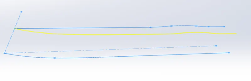
Surface loft:
Loft Surface Loft Surfaces are surfaces generated by multiple 3D Curves or existing edges creating a smooth tangency between the selected curves. Match Points are created between each selection denoting the orientation and path of the loft surface.
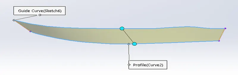
Surface trim:
Primarily used to cut away material from a surface, and provides two modes: Standard and Mutual. In Standard mode, a single selection is defined as a Trim Tool, and target surfaces are trimmed accordingly. In Mutual mode, multiple surfaces are trimmed with respect to each other.
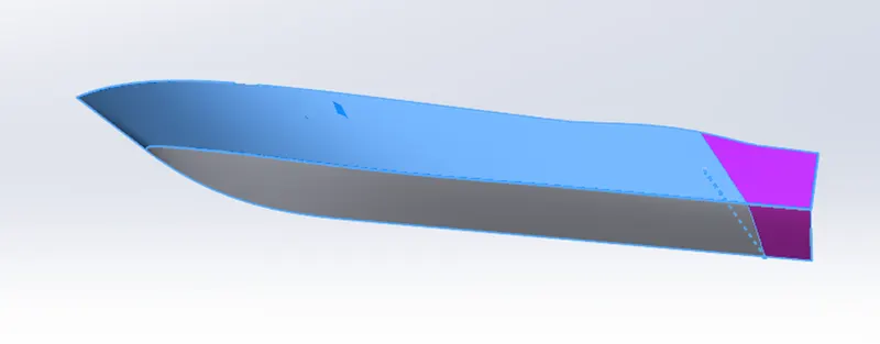
Surface extrude:
An extrude surface is extruded from a curve sub-object. It is similar to a surface created with the Extrude modifier. The advantage is that an extrude sub-object is part of the NURBS model, so you can use it to construct other curve and surface sub-objects.
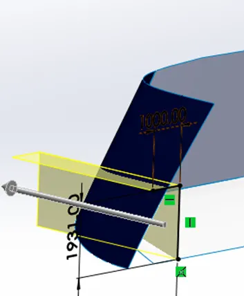
Shell:
The shell tool hollows out a part, leaves open the faces you select, and creates thin-walled features on the remaining faces. If you do not select any face on the model, you can shell a solid part, creating a closed, hollow model. You can also shell a model using multiple thicknesses.
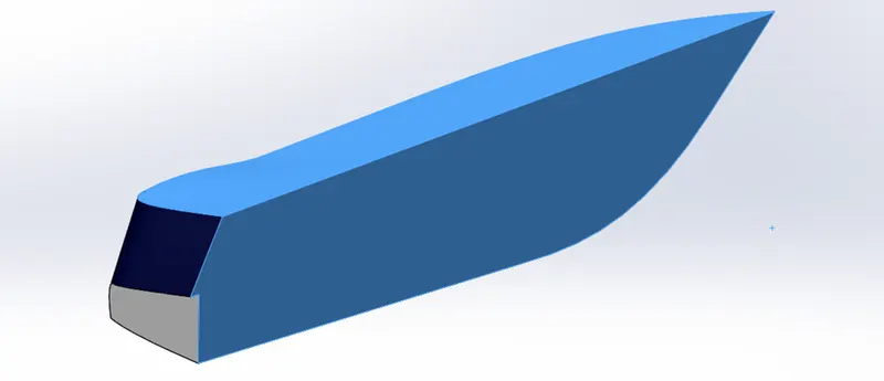
Chamfer:
Chamfer is used to make integration of two solid parts which intersect each other as same solid part.
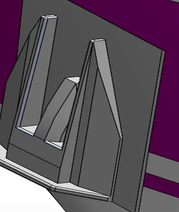
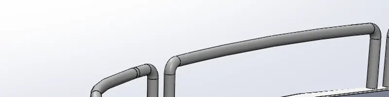
Sweep:
This feature is used to sweep any kind of fully defined sketch along with the plane.
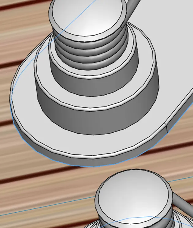
Dome:
Dome is a feature used to make dome shaped extrude including elliptical dome.
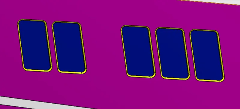
Linear sketch pattern:
Linear sketch pattern is part of Solid works sketch tools, which helps to create number of patterns from a sketch entity in linear manner. That means, if you have line in the sketch area and you want to create certain number of parallel lines with constant offset distance between them.
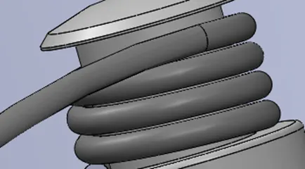
Helix/Spiral:
You define helix and spiral parameters in the Helix/Spiral PropertyManager. In a part, select a sketch that contains a circle. Click Helix and Spiral (Curves toolbar) or Insert > Curve > Helix/ Spiral. Specifies the type of curve (helix or spiral) and which parameters to use to define the curve.
Surface sweep:
Sweep surface are surfaces that are generated from a section curve positioned along a path. Parallel sweep is defined as a section curve moving along a guide path while maintaining the section curve to be parallel to the guide path.
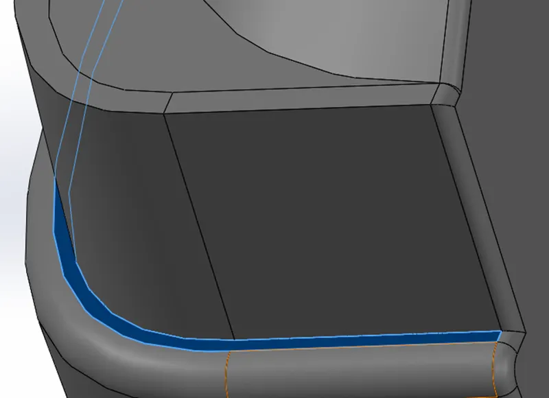
Surface knit:
Use the Knit Surface tool to combine two or more faces and surfaces into one. Edges of the surfaces must be adjacent and not overlapping. Surfaces do not need to be on the same plane. Select the entire surface body, or select one or more adjacent surface bodies. Knit surfaces absorb the surface bodies you used to create them.
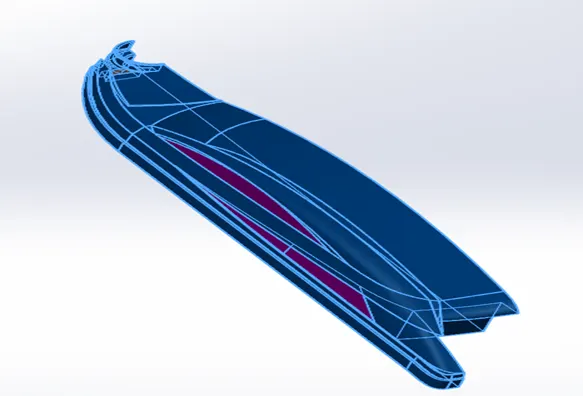
Ruled surface:
A ruled surface can be described as the set of points swept by a moving straight line. For example, a cone is formed by keeping one point of a line fixed whilst moving another point along a circle. A surface is doubly ruled if through every one of its points there are two distinct lines that lie on the surface.
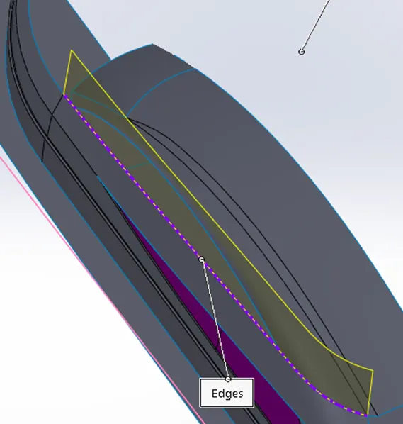
Surface fill:
One of the simplest things a Fill surface does is to simply fill a hole in a model. The hole might exist because it is the last gap in the modeling process, or it might be a hole that was created intentionally to get rid of a blemish in the model.
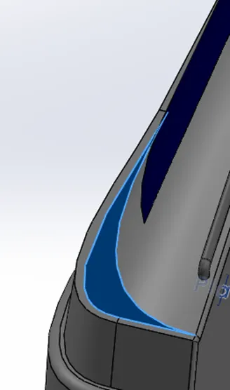
DESIGN PARTS EXPLAINED:
PROPELLER:
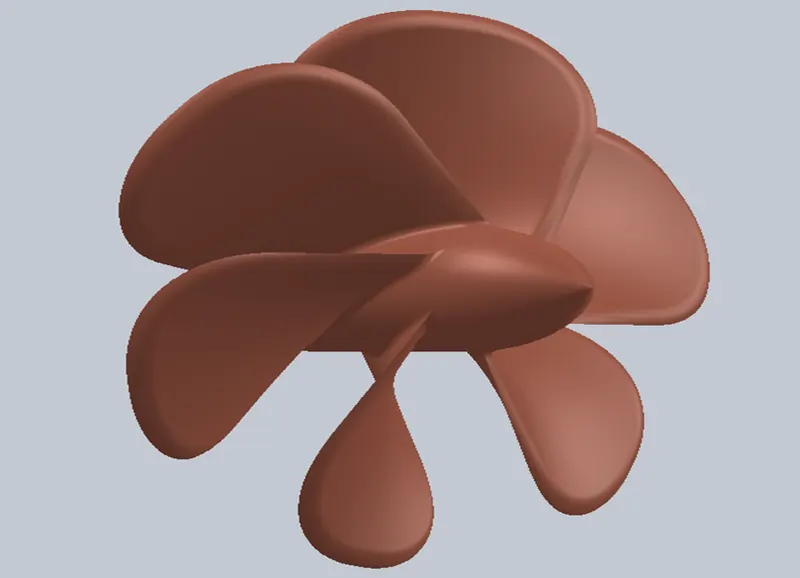
A propeller is a device with a rotating hub and radiating blades that are set at a pitch to form a helical spiral, that, when rotated, exerts linear thrust upon a working fluid, such as water or air.[1] Propellers are used to pump fluid through a pipe or duct, or to create thrust to propel a boat through water or an aircraft through air. The blades are specially shaped so that their rotational motion through the fluid causes a pressure difference between the two surfaces of the blade by Bernoulli's principle which exerts force on the fluid.[2] Most marine propellers are screw propellers with helical blades rotating on a propeller shaft with an approximately horizontal axis.The principle employed in using a screw propeller is derived from sculling. In sculling, a single blade is moved through an arc, from side to side taking care to keep presenting the blade to the water at the effective angle. The innovation introduced with the screw propeller was the extension of that arc through more than 360° by attaching the blade to a rotating shaft. Propellers can have a single blade, but in practice there are nearly always more than one so as to balance the forces involved.
RADAR:
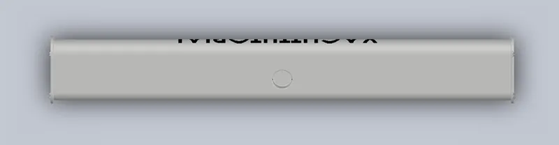
A marine radar device acts as a major navigation aid for boaters. It helps in detecting boats, birds, landmasses, and weather systems - even if the visibility is less than usual. The two fundamental features of a marine radar unit are transmitter power and beam angle.
HULL:
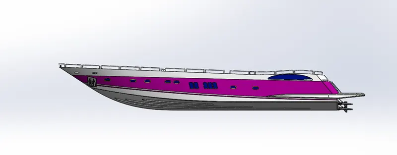
The hull of a ship is the most important as well as the most noticeable part of the ship. It is the watertight part of any vessel or even boat. It is defined as the water-tight enclosure of a ship. It protects the cargo and the machinery of the ship. It can also protect the boat from flooding and other structural damage. It is the part of the vessel which meets the ocean. The point or the line at which the hull of a ship meets the surface of the water is called the waterline.
GARAGE DOOR:
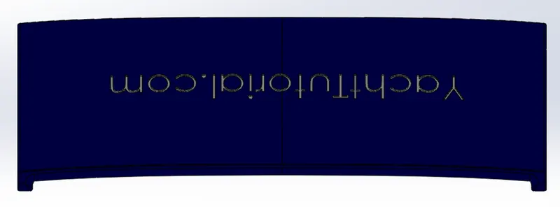
A garage door is a large door on a garage that opens either manually or by an electric motor. garage doors are frequently large enough to accommodate automobiles and other vehicles. Small garage doors may be made in a single panel that tilts up and back across the garage ceiling.
SUPERSTRUCTURE:
A superstructure is an extended construction of any building or platform that rises above the rest of the building or platform in a distinct manner. The word comes from a combination of two Latin words, the Latin prefix ‘super’ means in addition or above or in excess of, whereas the stem word ‘structure’ means to build or to heap up. Thus, superstructure means to add a construction to an already existing structure. In ships this is the name given to the part of the ship that emerges from the deck.
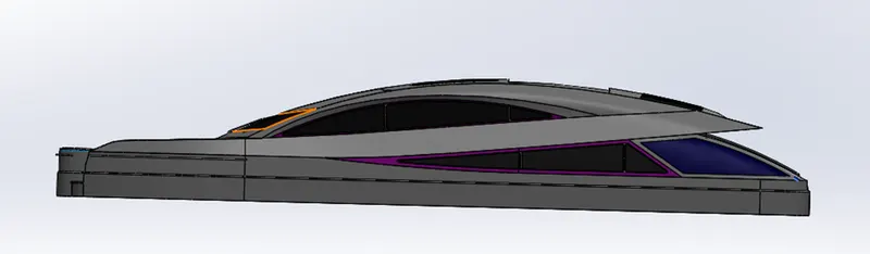
FRONT SEAT:
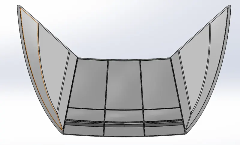
MIDDLE SEAT:
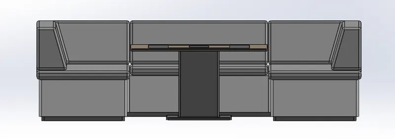
REAR SEAT:
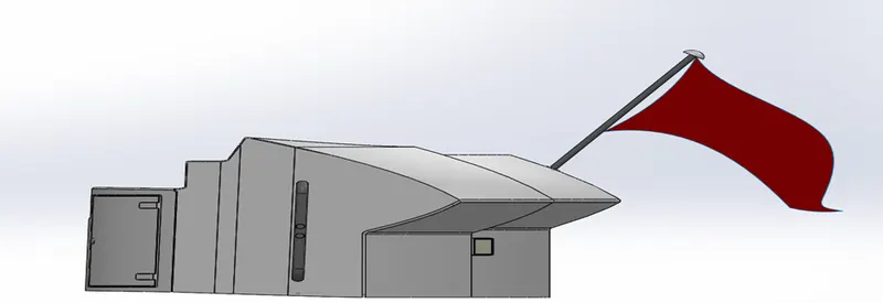
RADAR MAST:
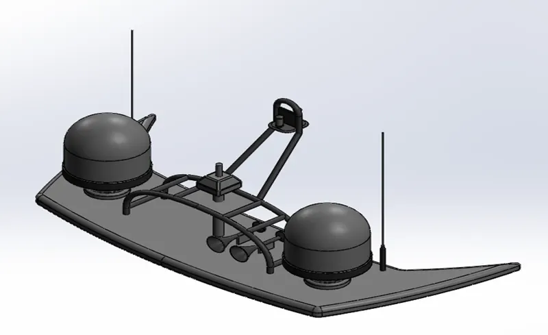
ASSEMBLY OF YACHT:
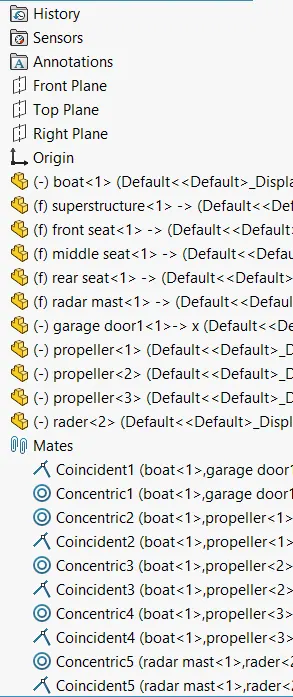
Build a complex assembly consisting of many components, which can be parts or other assemblies, called subassemblies. For most operations, the behaviour of components is the same for both types. Adding a component to an assembly creates a link between the assembly and the component. When SOLIDWORKS opens the assembly, it finds the component file to show it in the assembly. Changes in the component are automatically reflected in the assembly.
ASSEMBLY APPROACHES IN SOLIDWORKS:
1.Top-down approach
2.Bottum-down approach.
Top-down approach:
In top-down assembly design, one or more features of a part are defined by something in an assembly, such as a layout sketch or the geometry of another part.
Bottom-down approach:
You can create assemblies using bottom-up design, top-down design, or a combination of both methods.
FRONT VIEW OF YACHT:
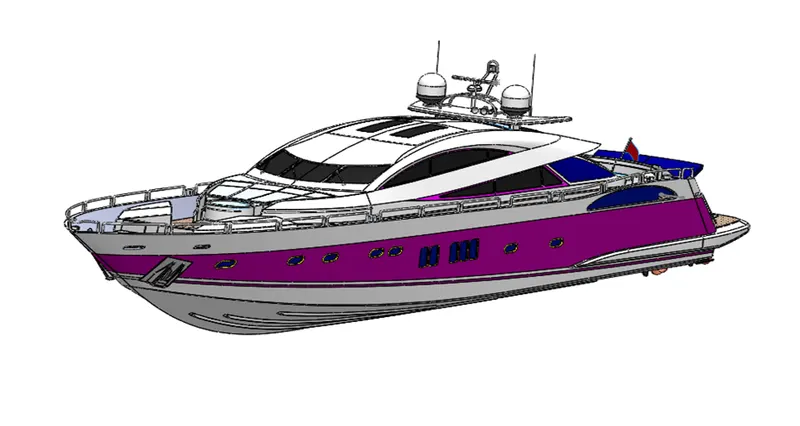
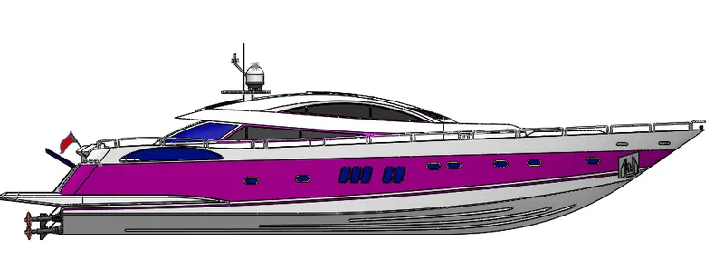
SIDE VIEW OF YACHT:
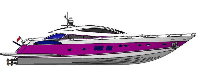
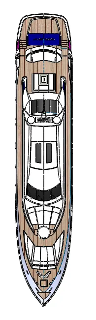
TOP VIEW OF YACHT:
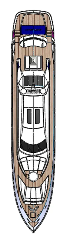
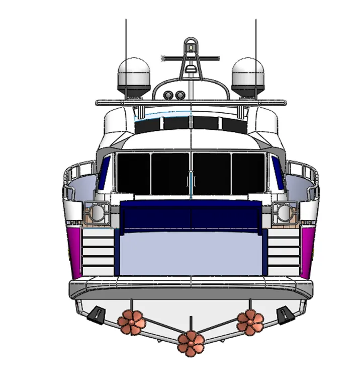
BACK VIEW OF YACHT:
RENDERINIG:
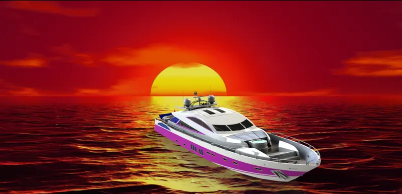
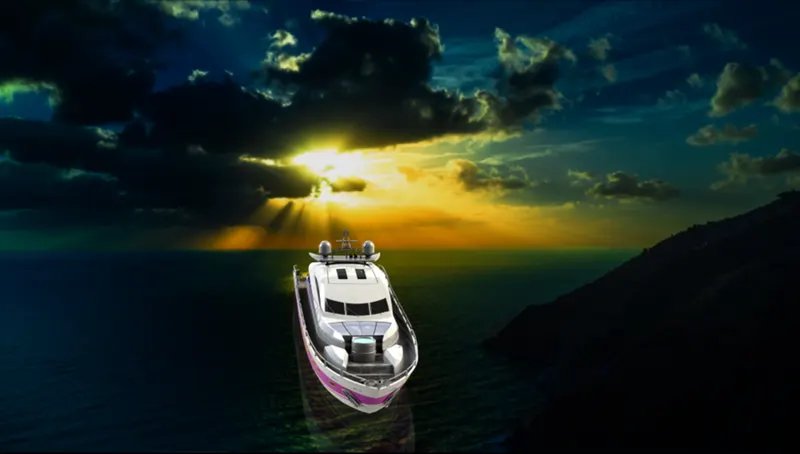
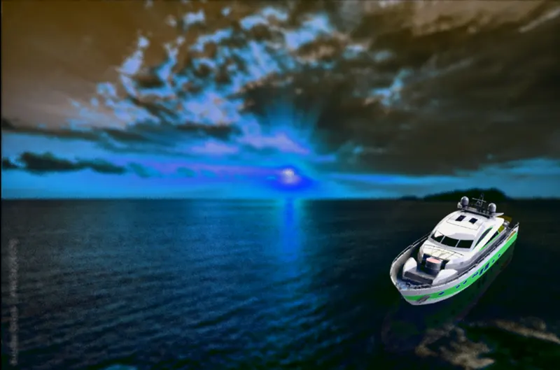
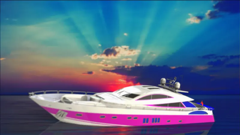
Photo View 360 allows you to create a rendering within the SOLIDWORKS window. When you mouse-click Render Tools and Display Manager, you will see options to create a scene, add and adjust lighting, and also the option to add a camera if you like. Once you’re finished, you can click on Final Render to invoke a Photo View 360 rendering.
Go-to rendering option you have is real view graphics. First, make sure that real view graphics is activated, and you are using an approved graphics card on your machine. Next, with your library content panel open, simply drag and drop the desired material, or appearance, from the panel on any part in your assembly.
CONCLUSION:
All the parts of the yacht are modelled and assembled together successfully using solid works.