Week 9 - Project - Master Section Development
PROJECT-1
MASTER SECTION (B PILLAR ) DEVELOPMENT
OBJECTIVES:
- Analysing the class A and performing necessary modification to obtain the modified class A.
- Creating the tooling axis .
- Performing draft analysis of class A surface.
- Creating the flanges with respect to the given MASTER SECTION.
- Obtaining the flanges and then creating class B surface.
- Creating the class C surface .
- Trimmimg the CLASS A,B AND C Surface for obtaining the final trim.
- Creating the closed body.
- Creating the attachments like Dog house, Locators and Ribs following the master section,
- Creating the Side core tolling axis.
- Performing the vigrous draft analysis and make sure all parts are clearing with positive and required draft.
- Final submission.
- ANALYSING CLASS A
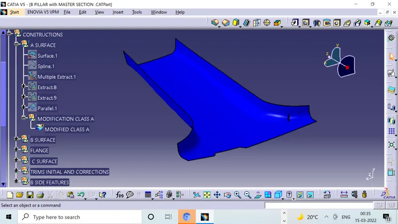
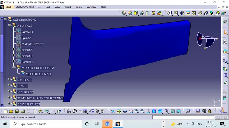
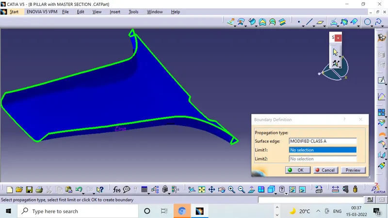
Since, there only one boundary for the given class A so its sure that the boundary is closed and we can further move to the next step of creating the tooling axis.
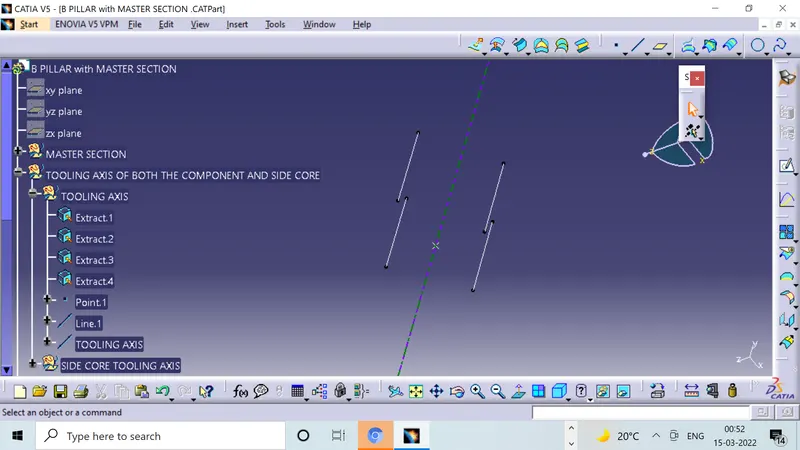
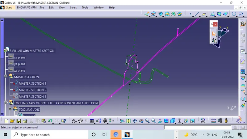
2. TOOLING AXIS CREATION
- Use the master section for creation of the tooling axis.
- Use the edges of the master section of the locator pins for creating the lines.
- Create the point for reference in between the edges.
- After creating the line bisect them , measure distance between them if its zero publish that particular line as tooling axis.
3)B SURFACE CREATION WITHOUT FLANGES
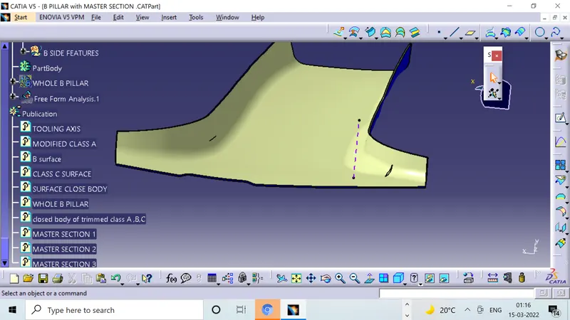
- Offset the A surface with the thickness of the component to obtain the B surface.
- As there are multiple variable fillets so by extracting and offseting we cannot obtain the required B surface
- So the direct offset is only way to obatin B surface.
4)CREATING THE FLANGES WITH MASTER SECTION
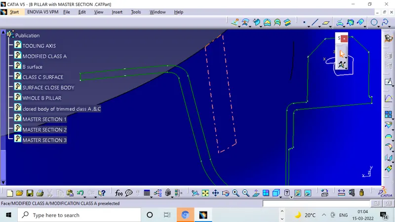
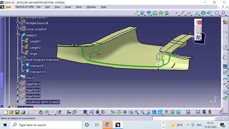
- The flanges are visible in the master section, we need to create the flanges from class A itself by extending class A.
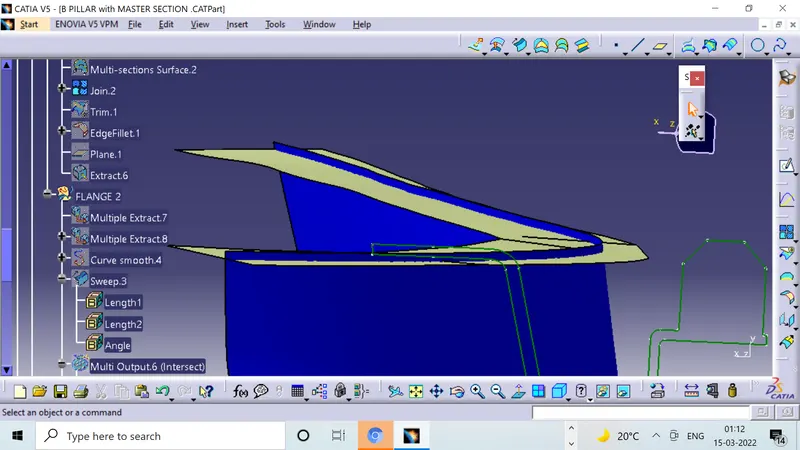
- The sweep with reference surface command is used for sweeping the extracted boundary of class A for obtaining flange.
- Use the master section for proper alligning the flanges, you can alter the angle for that purpose and make the master section parallel ith the obtained surface.
- Intersect the plane with the sweep obtained and master section to analyse briefly.
- Use parallel curve to get same curve along the class A as its starts from bit inner side of class A.
- Repeat the same thing to obtain the other side flange.
- Trim the flanges on both sides with A surface and then offset the flanges and trim it with B Surface to obtain the B surface with flanges.
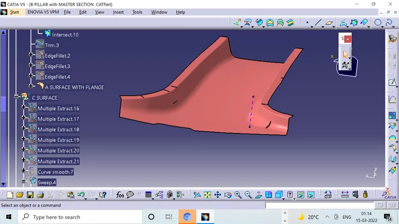
B SURFACE WITH FLANGES:
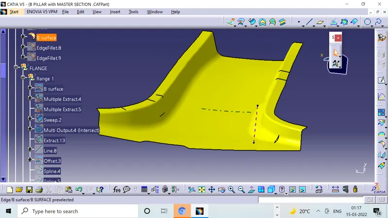
5)C SURFACE WITH FINAL TRIMS
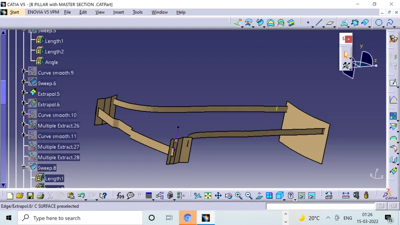
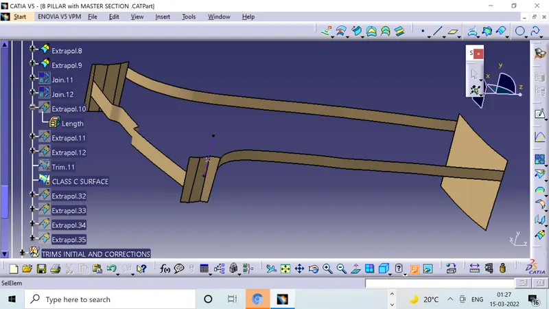
- Extract the boundaries into four parts of the class A surface.
- Sweep the attained guides after extracting by draft and draft the curve in such a way that it doesnt cuts A surface in layman term the draft must be positive when class A is positive.
- Extrapolate the sweeps and use multi surface command at few curves for obtaining curves and later trim whole to get the final C surface.
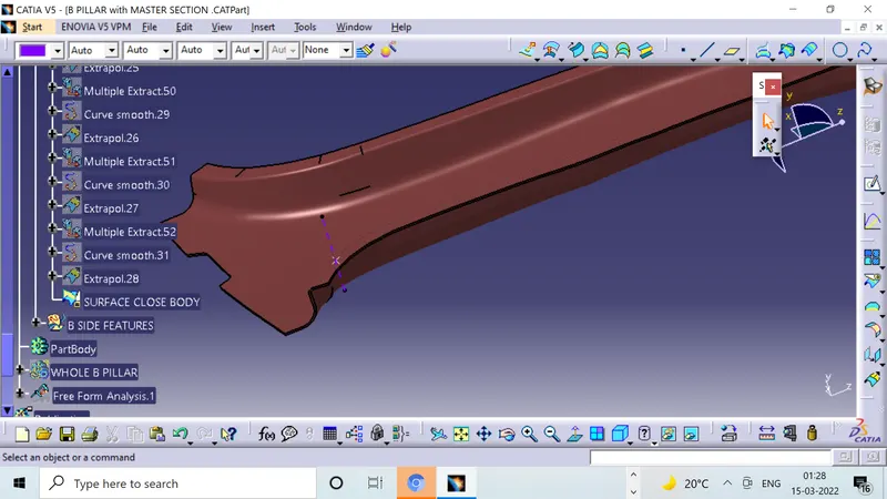
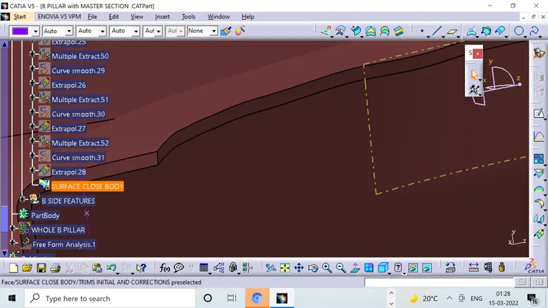
- Then trim the C surface with the A and B to obtain the final trim close surface.
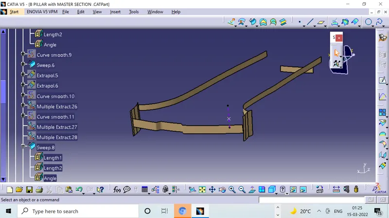
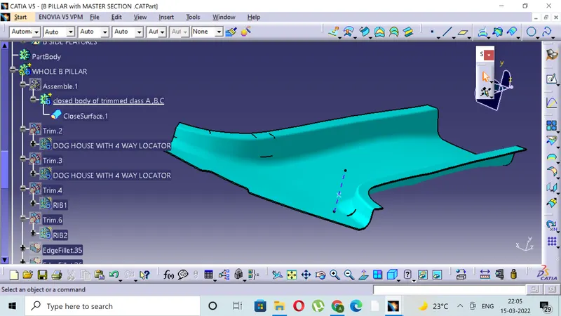
6)CREATING THE CLOSED BODY AND ASSIGNING IT AS MAIN BODY
- Move to the part window and with the help of surface based feature close the surface to get the closed part body.
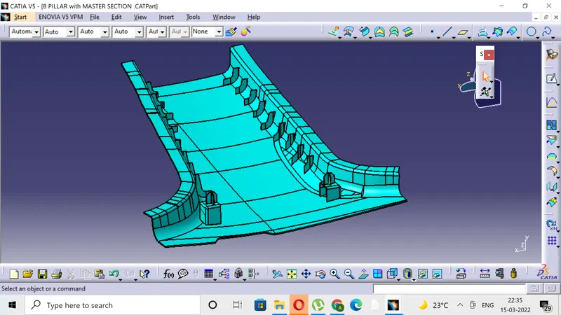
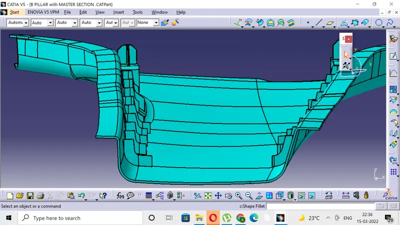
7)CREATING THE DOG HOUSE ,LOCATOR PINS AND RIBS.
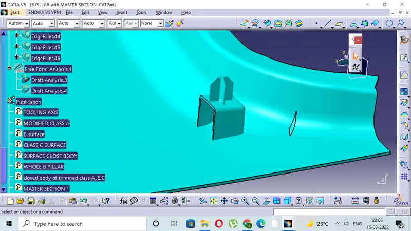
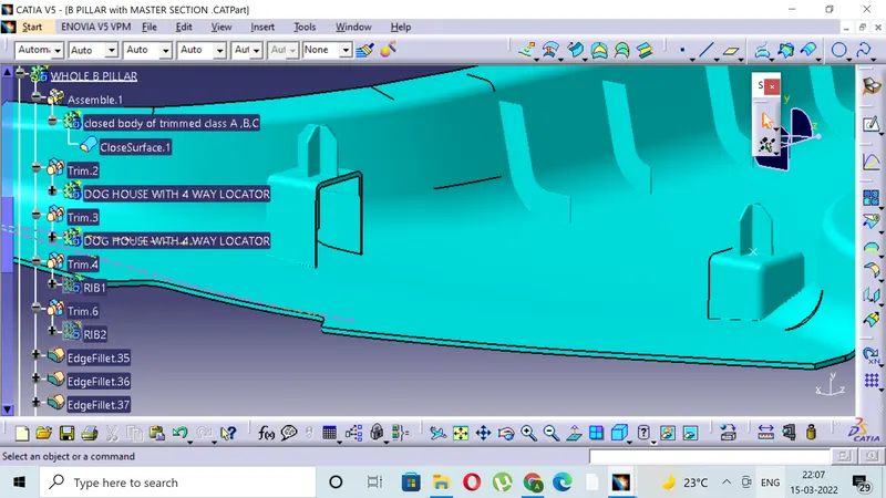
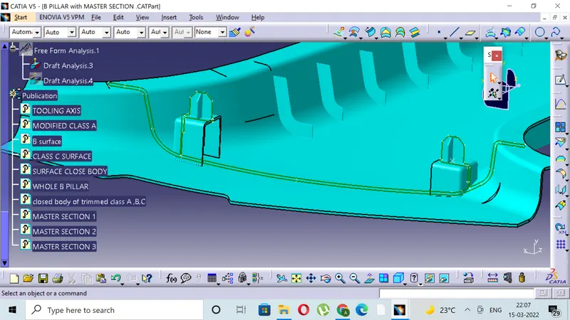
- Follow the master section for creation off the attchment features.
- Firtly create the geometrical sets for the creation of the dog house .
- Use edges and create the dog house following the master section.
- Extract the B surface , offset it obtain the inner side of dog house to follow the design rules for avoiding the sink marks.
- Trim and get the inner block, offset it and split it to get dog house.
- Ensure the peroper fillets to the dog house.
- Later over the dog house create the locator pin with use of the master section.
- Create the plane betwwen the flanks and obtain same this on other side ,later union trim with the partbody for grtting final trim.
- Create ribs which are 50mm apart on both sides fot providing the stiffness to the component.
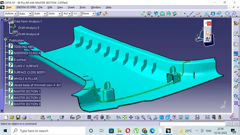
8)DRAFT ANALYSIS
1)COMPONENT
- The draft valuee for the component is given 3 degrees and the analysis is carried out.
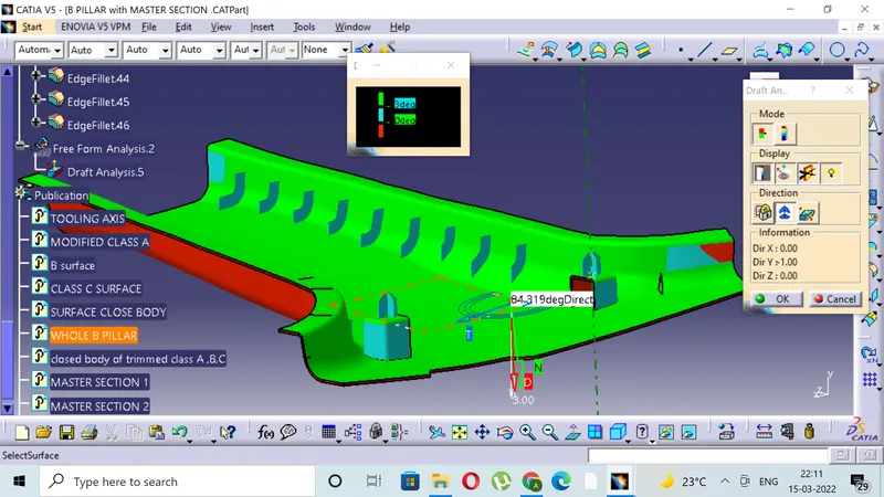
FOR THE COMPONENT FACING B SURFACE ITS GREEN WITH POSITIVE DRAFT.
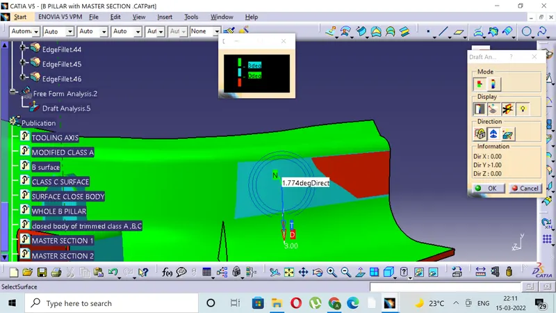
HERE THE CLASS A ITSELF HAS LESSER VALUE OF DRAFT AND SHOULD DE DISCUSSED FOR FURTHER ENTITLEMENT.
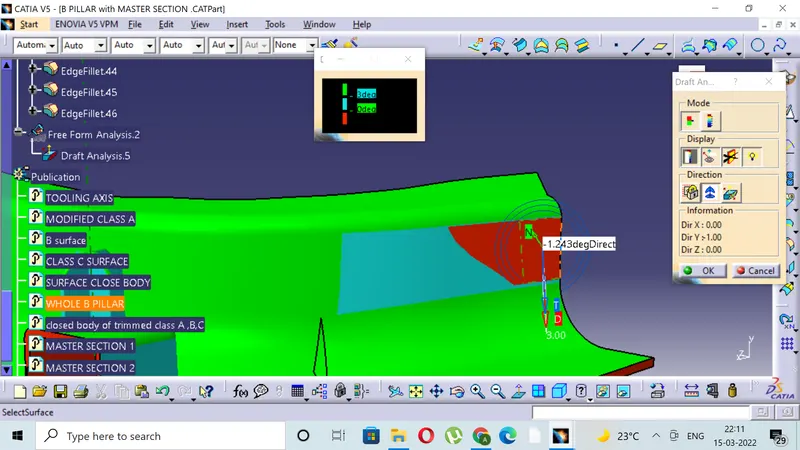
HERE THE CLASS A HAS NEGATIVE DRAFT SHOULD BE DISCUSSED WITH THE TEAM.
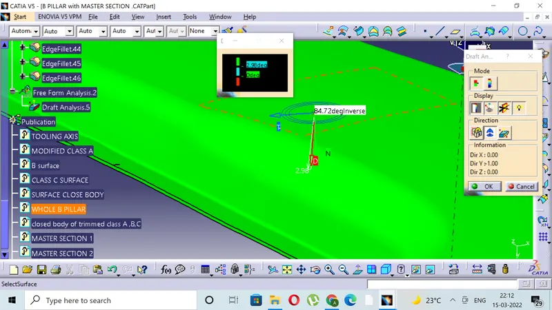
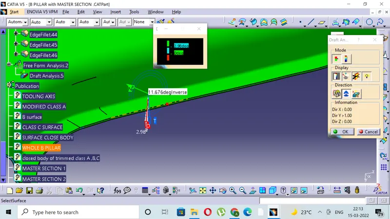
CLASS A IS POSITVE DRAFT WITH THE CLASS C SURFACE
2)ATTACHMENT FEATURES
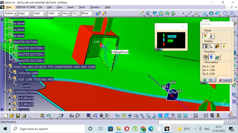
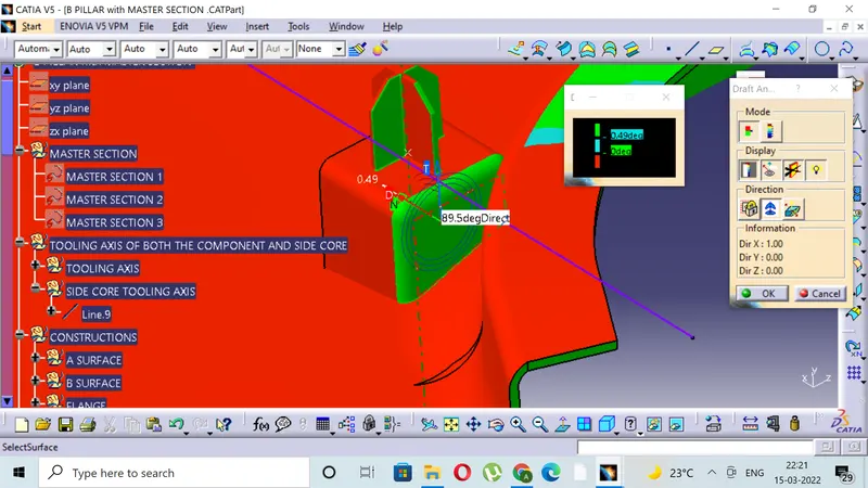
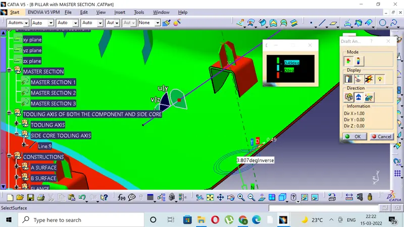
- FOR THE ANALYSIS OF THE ATTACHMENT FEATURES THE DRAFT VALUE IS GIVEN AS 0.5 DEGREES
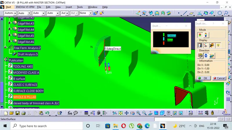
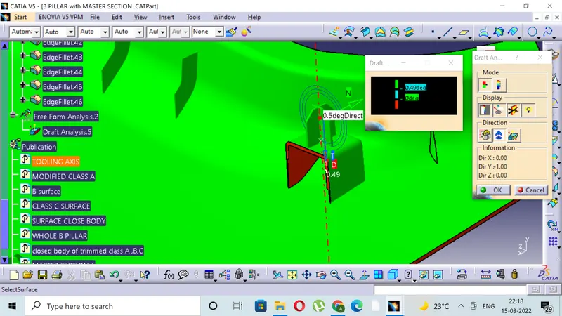
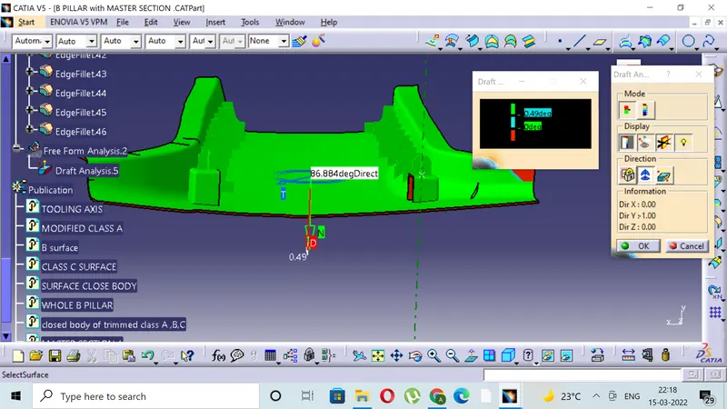
3)SIDE CORE ATTACHMENT FEATURE DOG HOUSE INTERNAL
HERE THE DRAFT VALUE IS GIVEN 0.5 DEGREES.

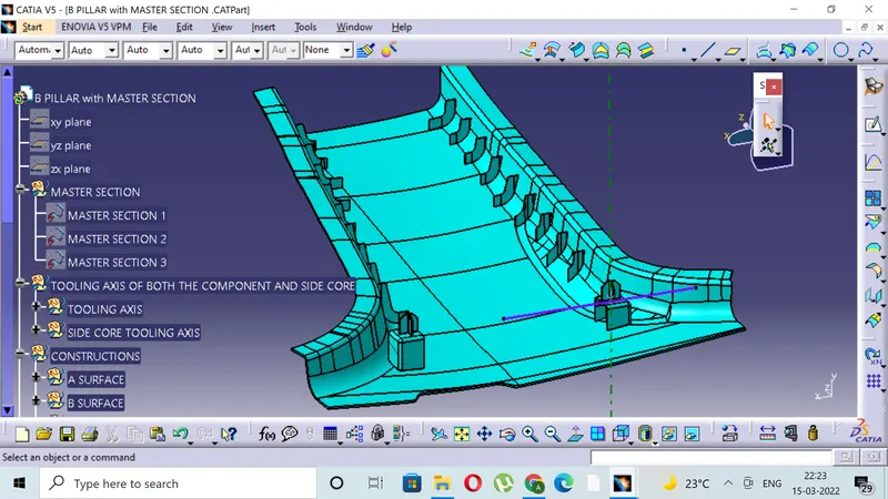
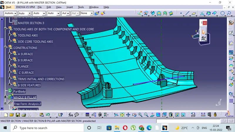
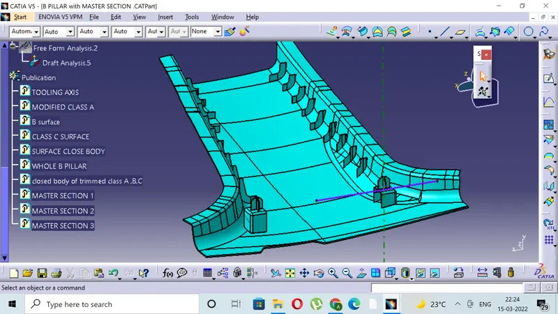
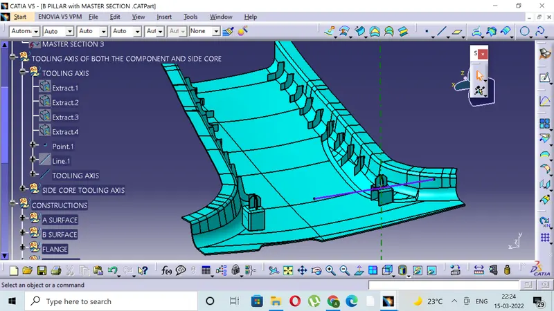
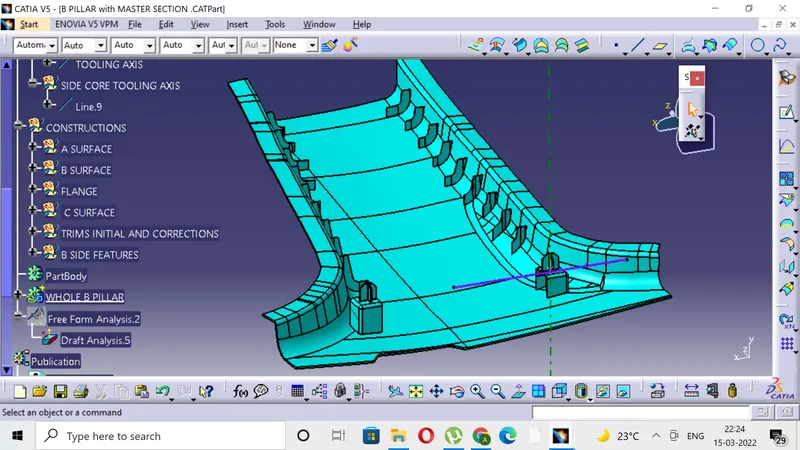
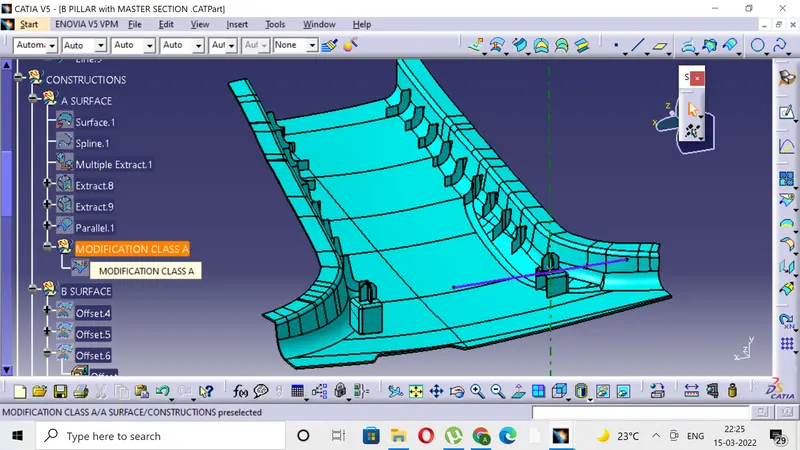
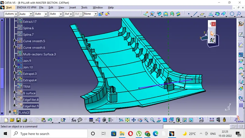
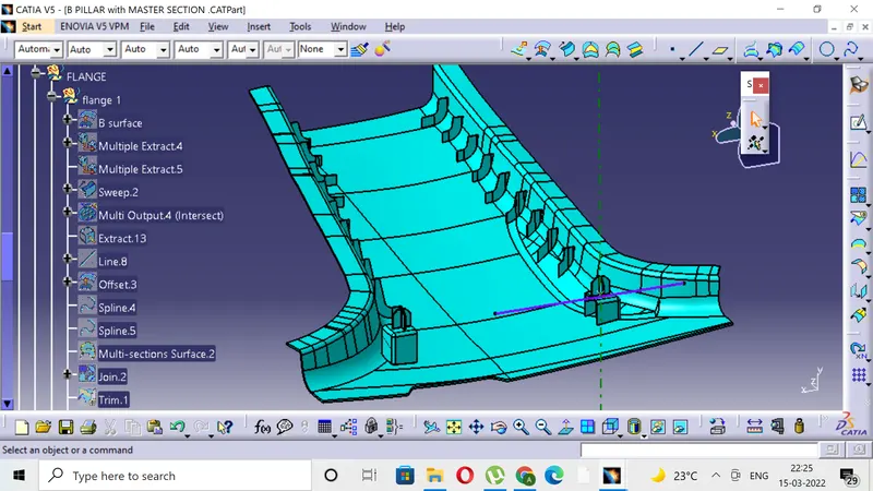
9)DETAILED TREE STRUCTURE.
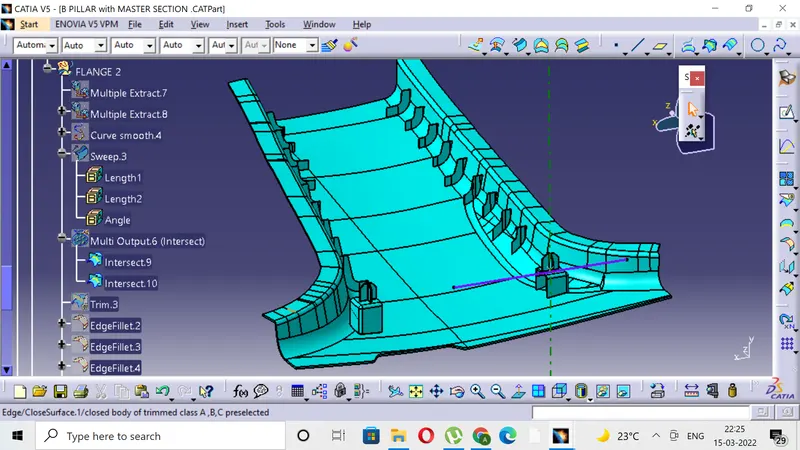
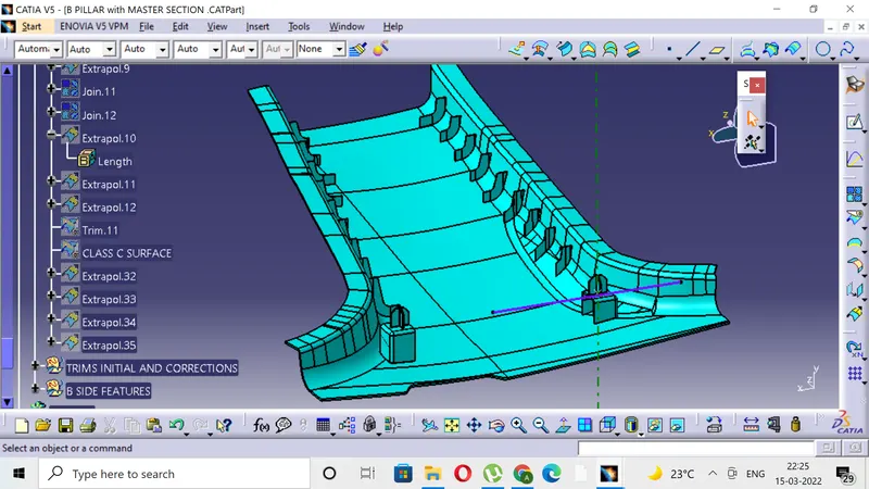
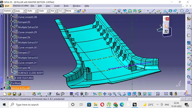
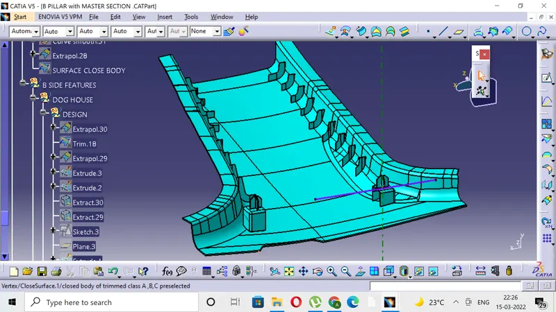
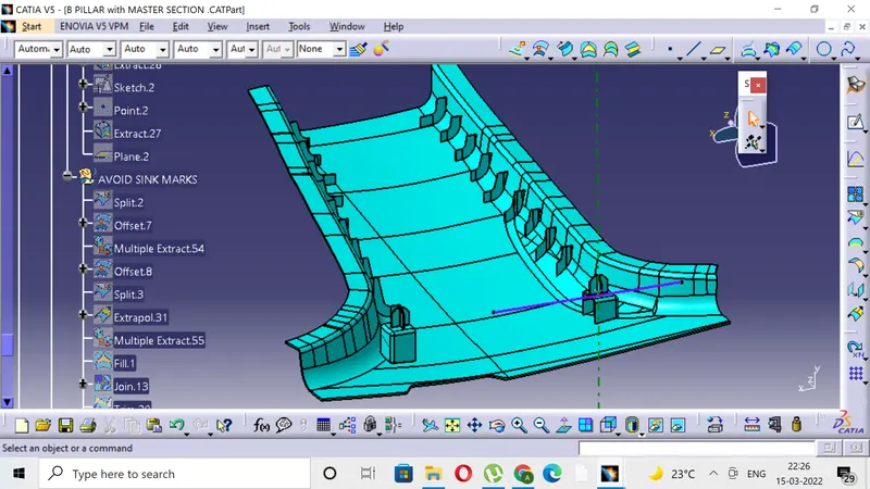
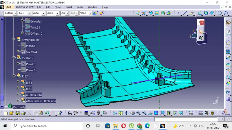
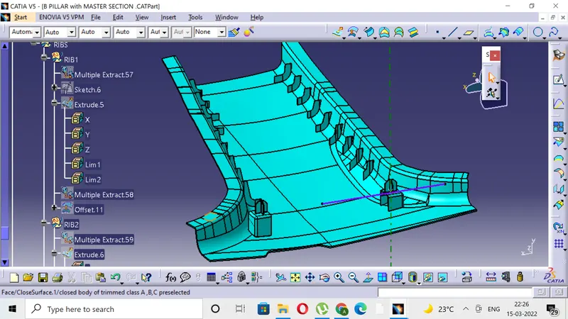
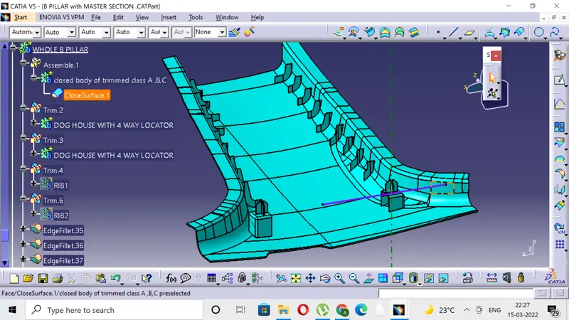
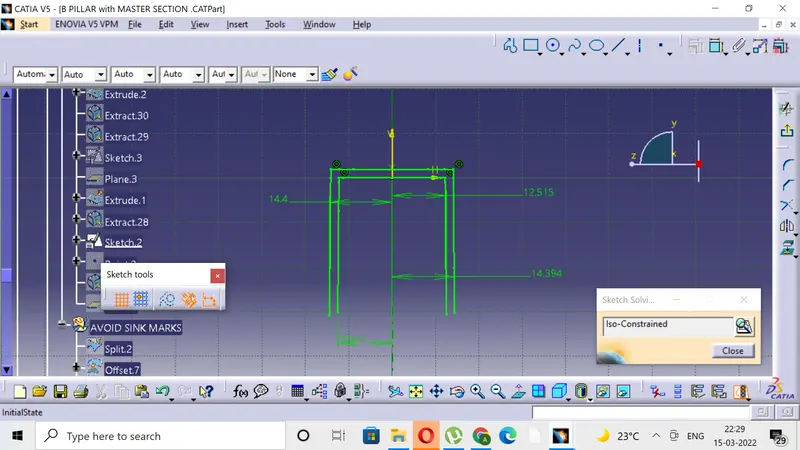
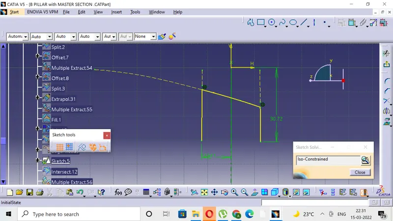
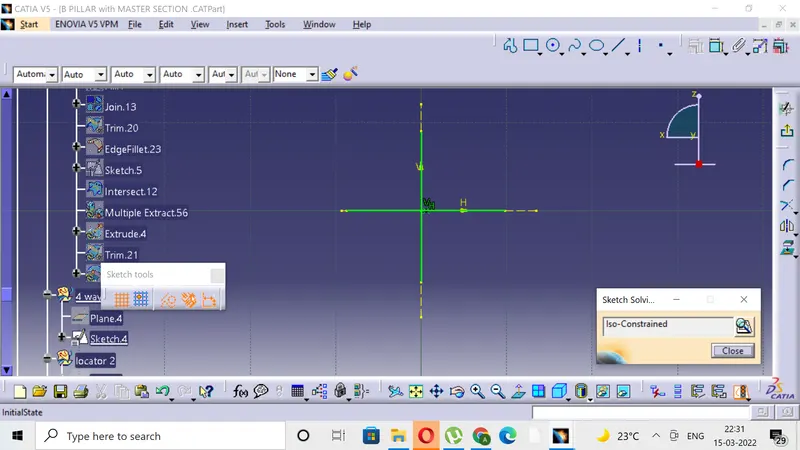
ISO CONSTRAINED SKETCHES .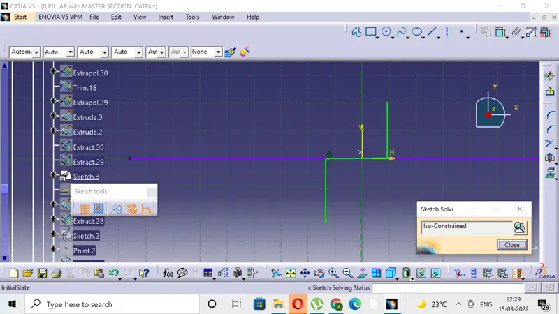
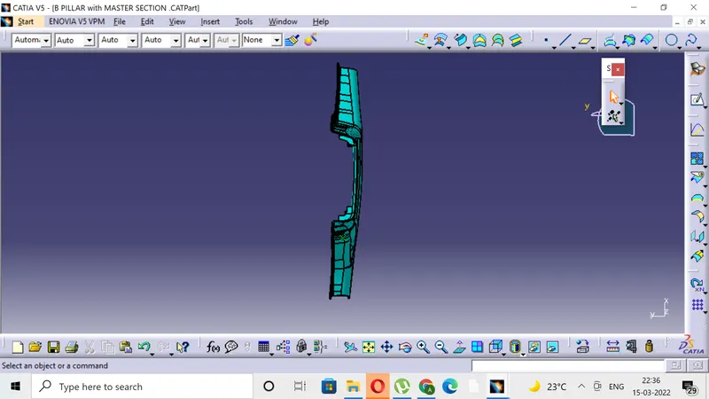
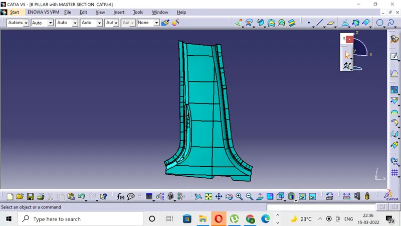
VIEWS :