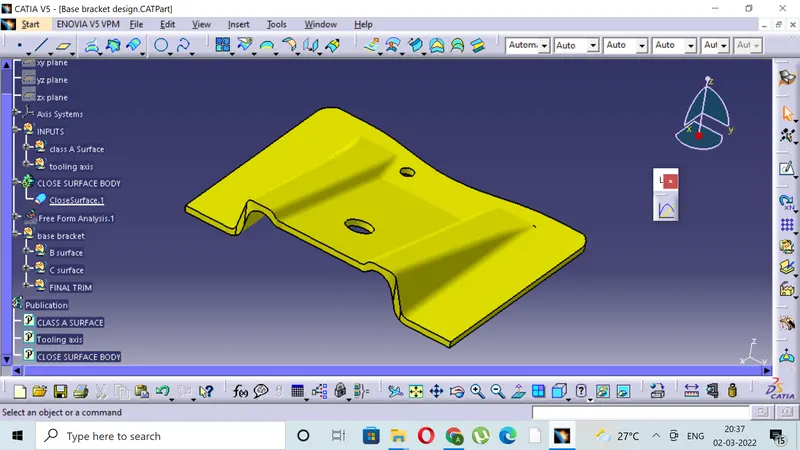
Week 8 - Challenge 2 - Base Bracket Design
BASE BRACKET DRAFT ANALYSIS
THIS IS THE CHALLENGE OF THE SURFACE AND PART WORKBENCH , WHERE MOST OF THE WORK IS PREFFERED TO BE DONE IN THE SURFACE WORKBENCH.
KEY TASK ACCOMPLISHMENT / OBJECTIVE .
- Create the tooling axis direction for the opening of the core and cavity.
- Create the class B surface for the attachment.
- Create the class C surface for the providing thickness to class A surface.
- Creating the closed body from the surface body.
- Draft analysis of class A and closed body.
INPUTS:
- We have class A surface as the input for accomplishing all the key targets mentioned in the objective as a plastic product designer.
TOOLING AXIS CREATION :
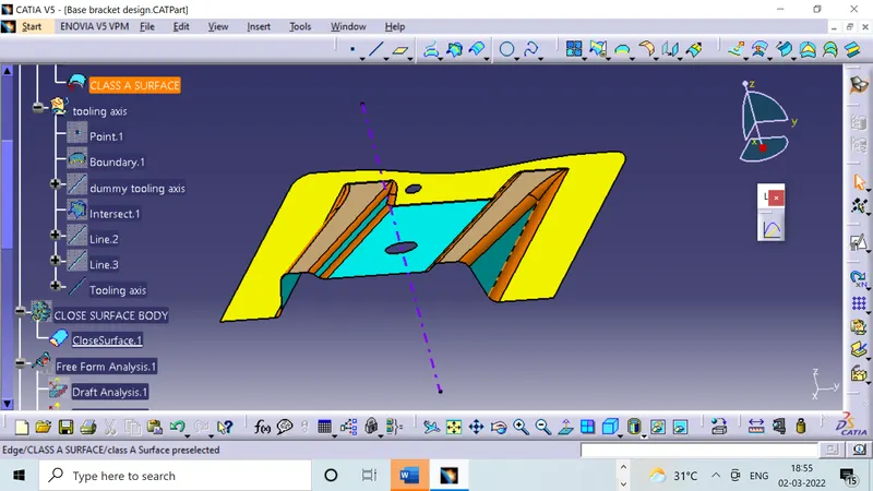
- The tooling axis direction is very much important from the design point of view as it decides the direction of moulding or opening of core and cavity.
- One should visualize the component in all 3-Dimensional axis and decide the probable dummy axis which is Z axis for base bracket.
- Next task is to check the clearance of the respective component with draft in both zx and yz planes.
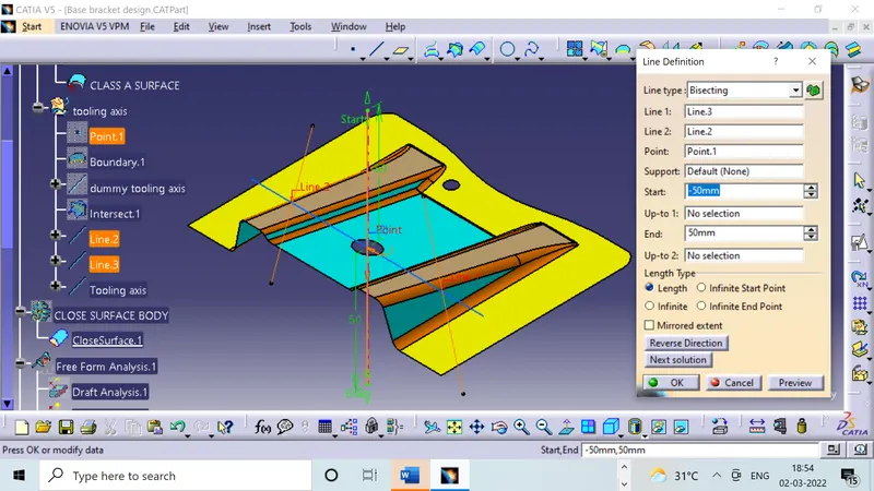
- Create a point centre to the surface / circle of the hole and create the axis system.
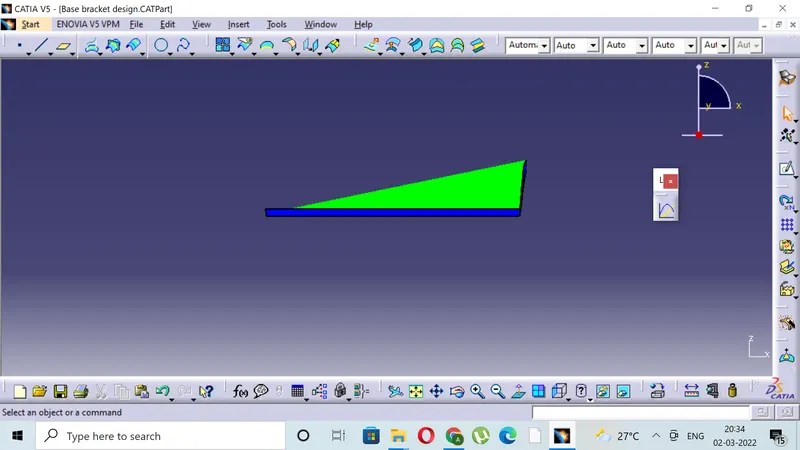
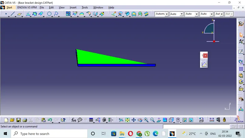
- using the intersect command intersect the yz plane with the class A to get the clearance details in the yz plane .
- extend the draft edges and create the bisecting line to get the tooling axis in the yz plane.
- The component is cleared in zx plane visually as there are no slots and holes, which will not affect the moulding direction.
CREATING THE CLASS B SURFACE:
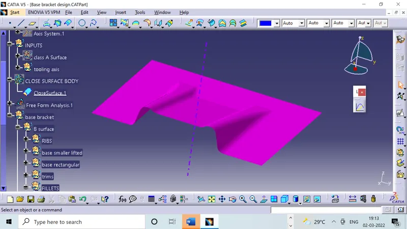
- Class B surface is the surface which is created with the help of class A surface as the reference.
- The the class B surface is the surface where all the necessary attachments and supports of the component is made .
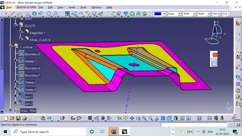
- The main parts without the edge fillets are extracted and untrimmed and then they are extrapolated for better view.
- The extrapolated parts are then made offset with reference to the class A with the thickness of the component, here thickness of the component for base bracket is 2.5 mm.
- The offset surfaces are then trimmed to attain the class B surface.
- The final class B surface must have the edge fillets similar to the class A and fillets must be given properly with a thought of maintaining same thickness throughout avoiding the flow line defects.
CREATION OF CLASS C SURFACE:
- The class C surface is the surface which is created to provide thickness to the class A surface with the help of class B surface.
- The class C surface is the middle portion of the class A and class B surfaces.
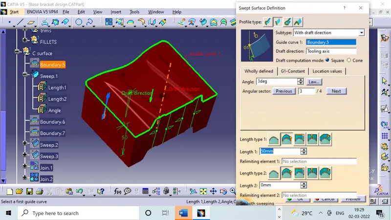
- The class C is created with the help of the sweep command in surface workbench.
- The class A surface's boundary is taken as profile (guide curve) and then tooling axis created is taken as direction of the sweep in subtype draft direction
- The draft angle for the sweep is 3 degrees.
- The holes are created using the same axis and draft angle.
- The attained sweep is joined with class A surface to obtain the class C surface.
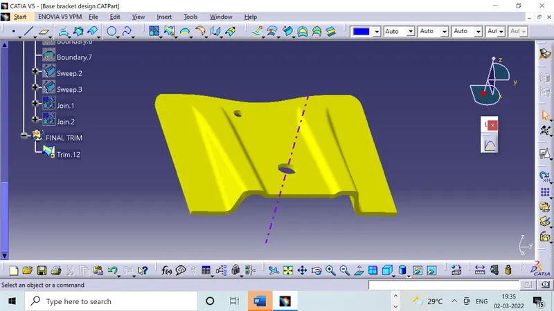
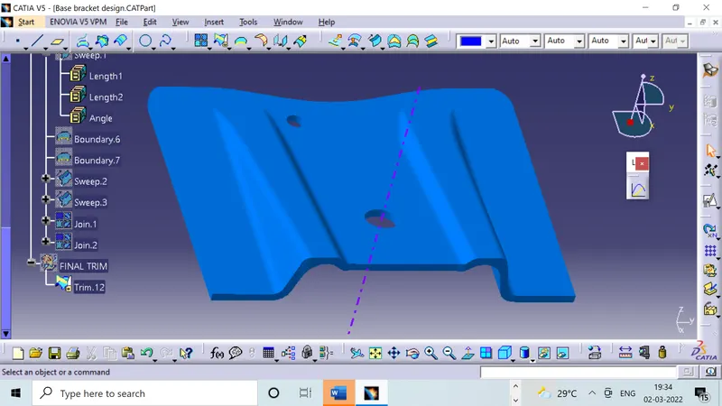
- The final trim is obtained by trimming the class B with the class C surface.
- The final check to ensure the proper clossness of surface with the boundary command .
CLOSED BODY CREATION:
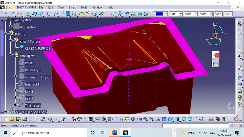
- The final trim surface is then openend in the part workbench for providing the closed surface for analysis.
- The surface based feature in the part workbench is utilized for creating the closed surface.
DRAFT ANALYSIS OF THE CLASS A AND CLOSED BODY :
- The draft analysis is done to ensure that the draft in permeasible with the design consideration.
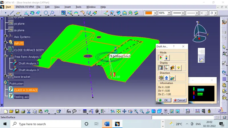
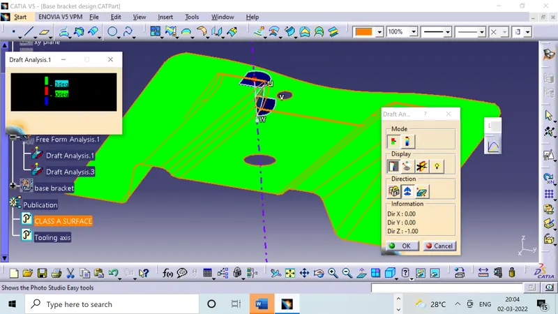
- The draft analysis is done by changing the visualization mode to customize and select shading as material.
- The draft based feature enables us to visualize and examine the draft.
- The draft window is has two tables one is for examining the draft and other one is the colour code.
- The draft value is set in the colour code window with each colour having their own significance.
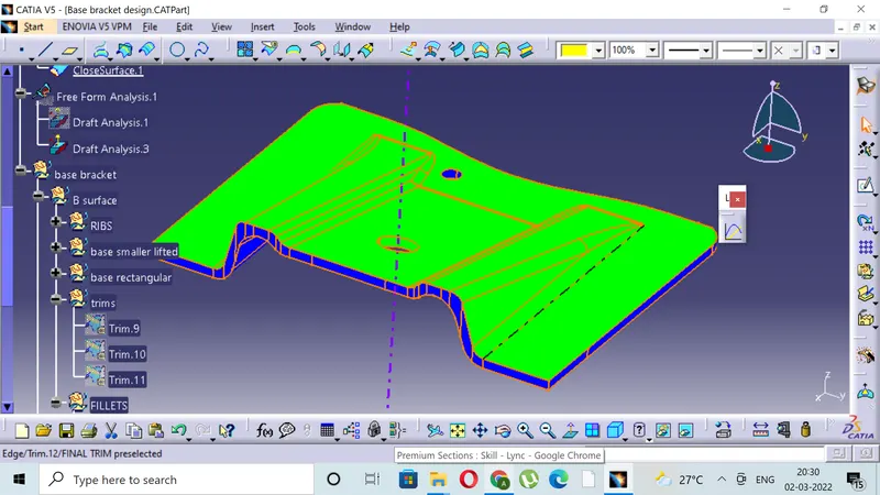
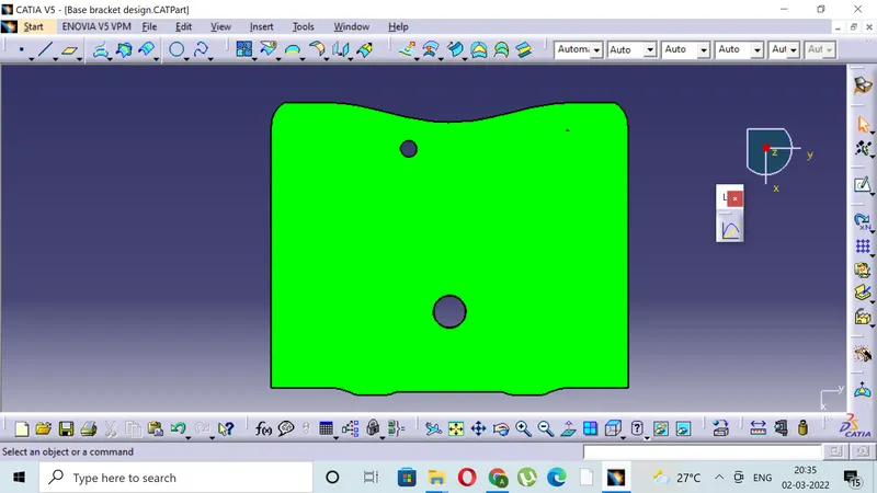
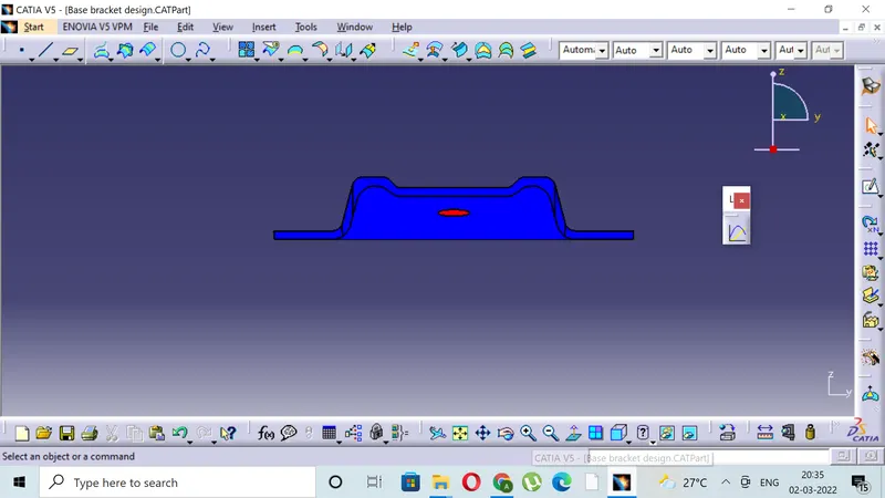
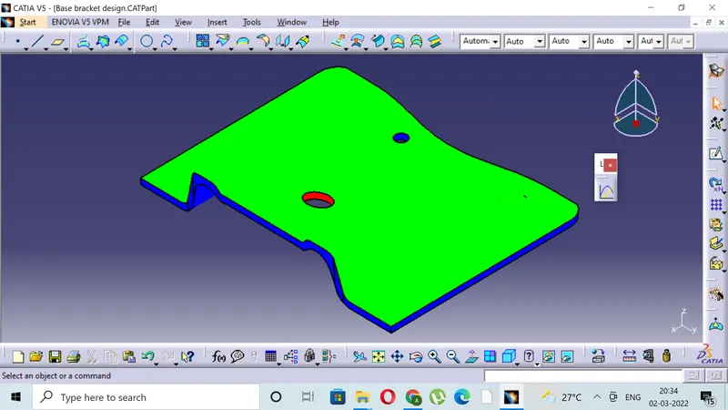
- The red colour indicates the positive draft less than minimum draft where as the green colour indicates the minimum draft.
- The blue colour indicates the negative draft.
- For visualizing the draft the compass is aligned with the tool axis direction and the cursor is then made clicked upon the surface for viewing the draft.
- The quick view in display window enables to examine the draft value throughout the surface.
- Here both class A and closed body are given the minimum draft as 3 degrees.
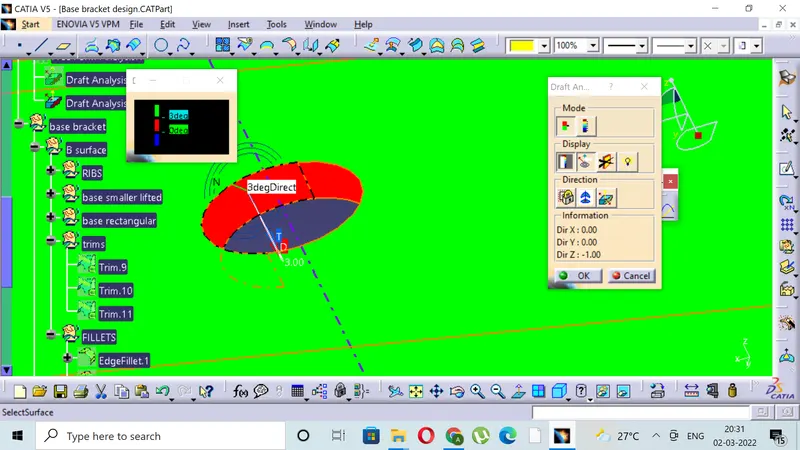
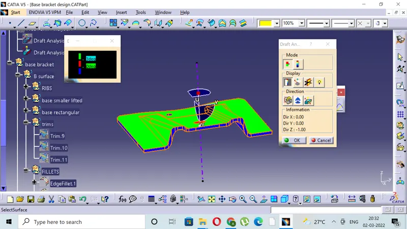
DRAFT ANALYSIS OF THE CLOSED BODY IN ALL THE VIEWS:
TREE STRUCTURE WITH PUBLICATION