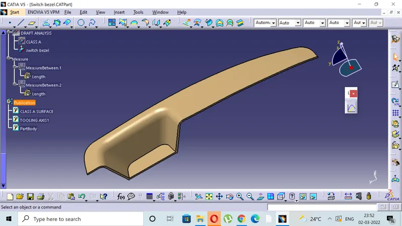
Week 8 - Challenge 3 - Switch Bezel Design
DRAFT ANALYSIS ON SWITCH BEZEL
OBJECTIVE:
- Analysing the class A surface given as input.
- Create the tooling axis for the core and cavity opening.
- Create the B surface for the given class A surface.
- Create the C surface with the help of class A and class C surface.
- Creating the solid closed component with the help of closed surface based feature.
- CLASS A SURFACE
The class A surface is the surface created from the concept sketch in the software called AutoDesk ALIAS, the class A surface is basically the styling surface and it is used as reference by the product designer to design the component with the help of tooling axis and draft analysis, here we have switch bezel as a class A surface.
2. EVALUATING CLASS A
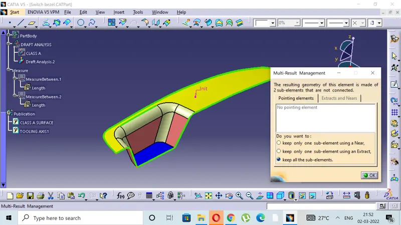
After receiving the class A surface the next step is to affirm about the closeness of the class A surface means make sure the class A surface is closed properly and there is no open surface which will hinder the analysis procedure in subsequent processes.In catia you can acknowledge this by using the Join and Boundary command .
3 . TOOLING AXIS CREATION
- Tooling axis plays important role in plastic product manufacturing and designing, this axis decides the direction in which mould is going to work while production of the component.
- The main focus while deciding the tooling axis is clearing the component in the moulding in the same axis with the minimum use of the side core for producing the component, the side core usually adds up to the cost of the component.
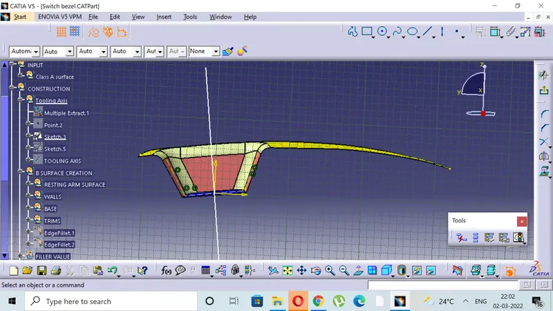
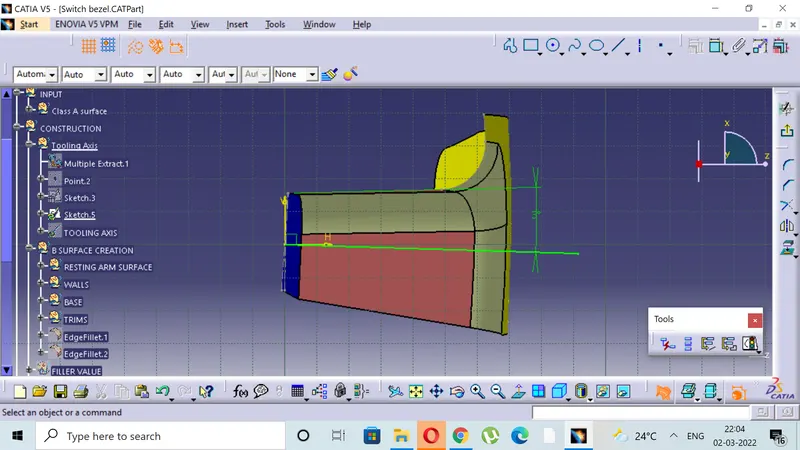
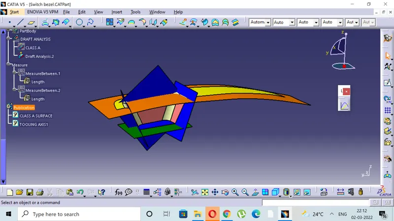
- For the particular component X,Y and Z can be the possible direction for the tooling axis.
- You must specify the axis system by creating the point on the surface.
- With the help of the intersect in the YZ plane create the tooling axis in YZ plane .
- With the help of the intersect in the ZX plane create the tooling axis in ZX plane.
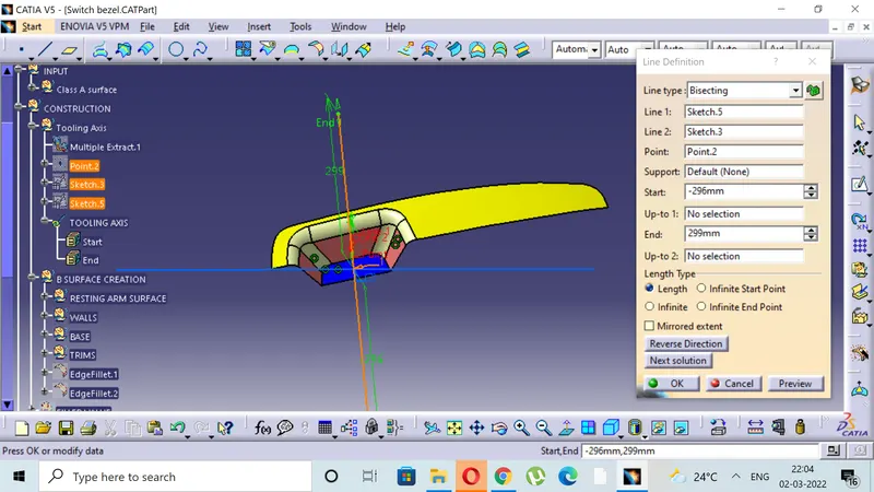
- The last step is to bisect the two tooling axis to obtain the main tooling axis of the class A surface.
4.CREATING THE B SURFACE
- The B surface is the surface where all the necessary attachments and supports are made for the component.
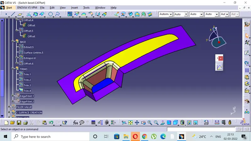
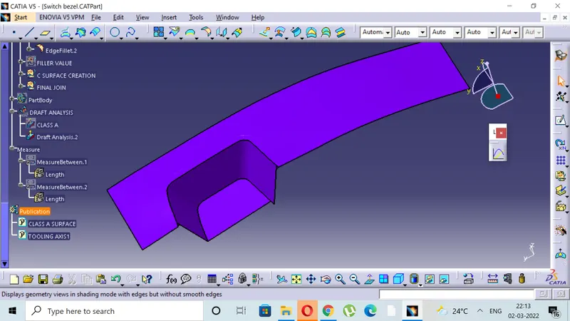
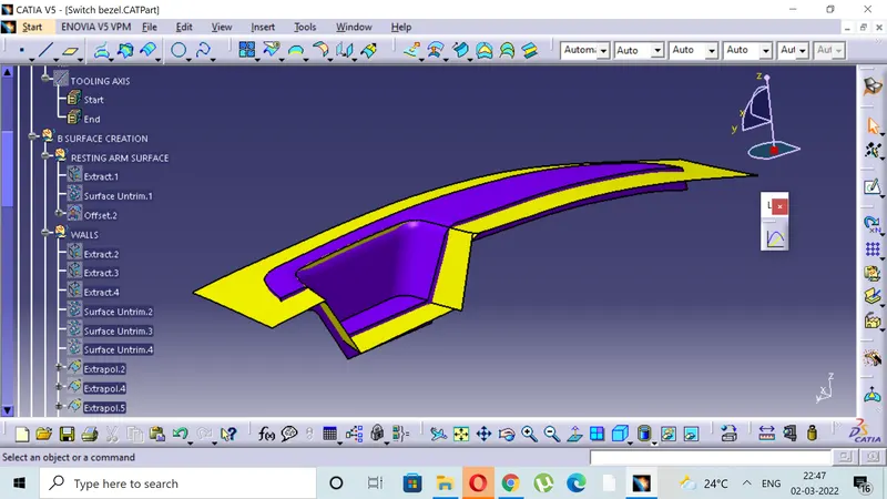
- The B surface is created using the class A as reference and extracting the major surfaces without the edge fillets.
- The extracted surfaces are then extrapolated to get the better view for trim,then offset these surfaces to the thickness of the component and then trimming the surfaces to get the B surface.
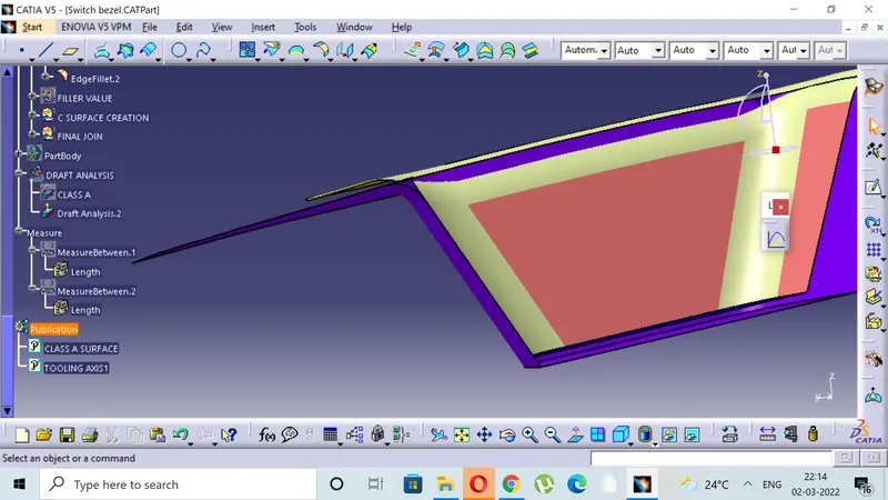
- The necessary trimmed surface must contain the edge fillets as class A surface.
- The edge fillets provided to B surface must be given properly to maintin the constant thickness throughout the component so as to avoid the flow line defects.
5)CREATING THE C SURFACE
- The C surface is the surface which is responsible for providing the thickness to the component.
- The C surface is the intermediate between the class A and class B surfaces.
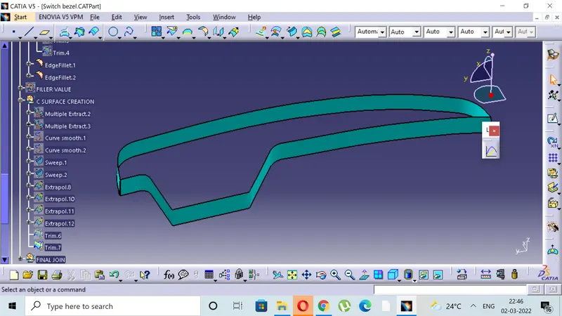
- The C surface is created by extracting the class a with two boundaries .
- Each boundary is then used as guiding curve for sweep command in draft direction subtype.
- The direction of the sweep is same as the tooling axis.
- The draft of 3 degree is given to both the sweeps.
- Complete the surface by extrapolating and trimming.
- Use the smooth curve to ensure the proper surfaces, you can smoothen the surfaces prior to join command.
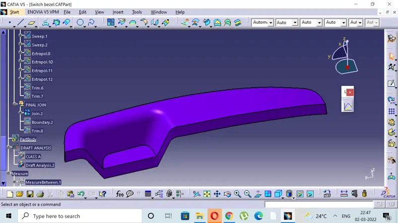
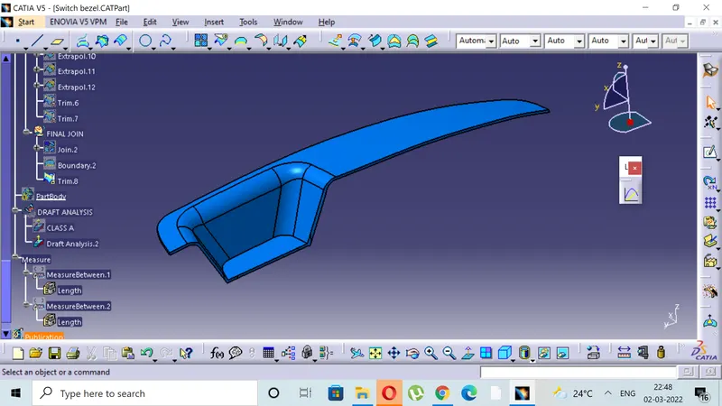
- Join the class A surface with the class C and then trim the join with the class B to obtain the final thickness component, here the thickness is 2.5 mm.
- Use the boundary command to ensure surface is closed and there is no multiple boundaries , you can alter if any by increasing the merging distance till 3 microns.
6)CLOSED BODY CREATION:
- Closed body is the body created in the part workbench with the help of surface based feature in the insert section.
- The draft analysis is done on this close body.
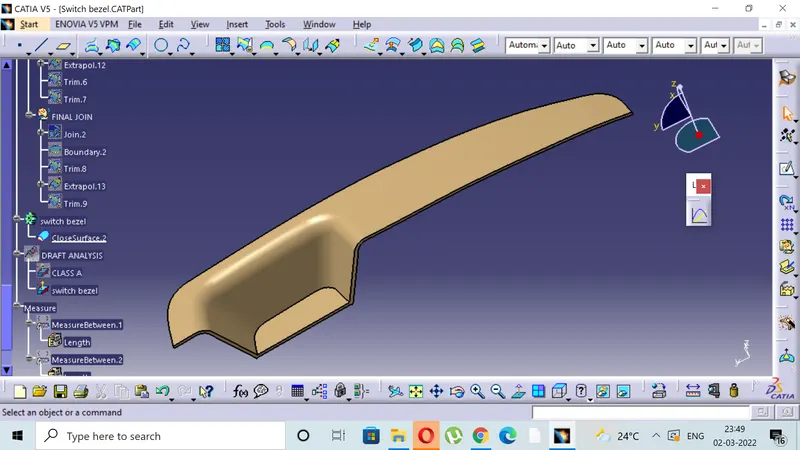
5. DRAFT ANALYSIS OF THE CLASS A AND CLOSED BODY
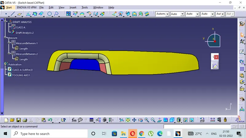
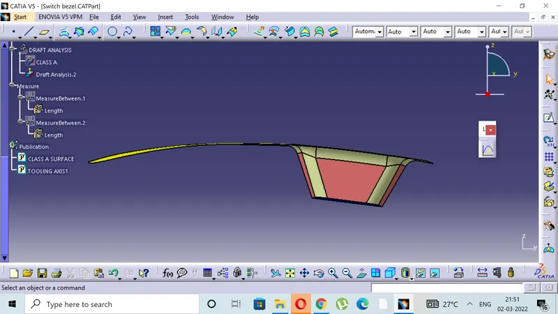
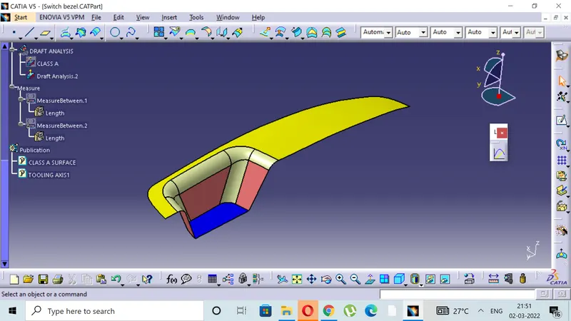
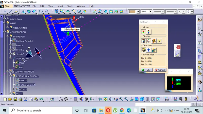
The draft analysis is very important tool as it helps the user to analyse the draft at various surfaces , the draft analyzer in catia uses the colour codes for the identifiction of the draft. Each colour has its own meaning for minimum draft ,negative draft and under draft
KEY PROCESS:
- VISUALIZATIION MODE: In the visualization toolbar change the shading with edges to the customization view and make shading specification as material to avoid the predictable pop-ups.
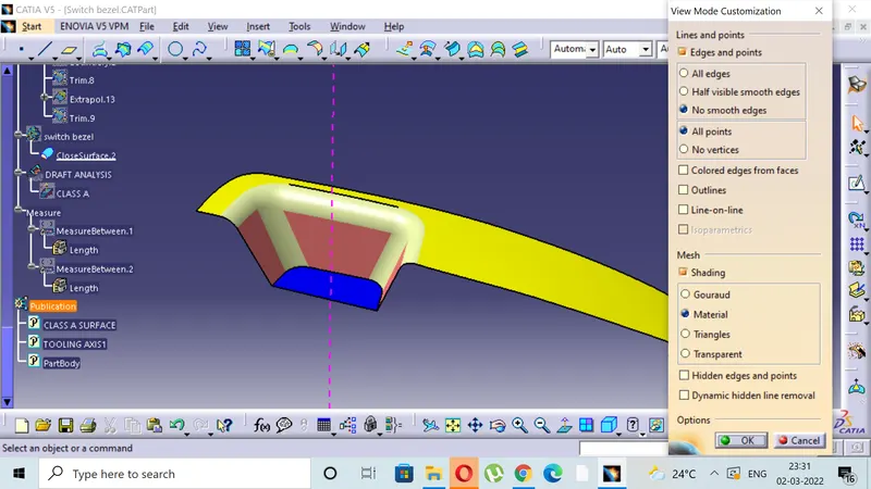
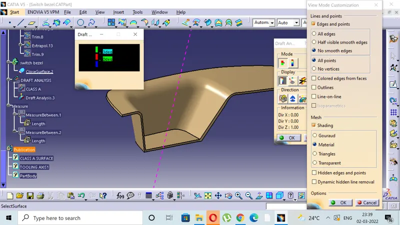
- DRAFT ANALYSIS TOOLBAR: Go to the insert workbench and click on analysis << feature based analysis , you will get into the draft analysis toolbar having one colour section toolbar for edits and values.
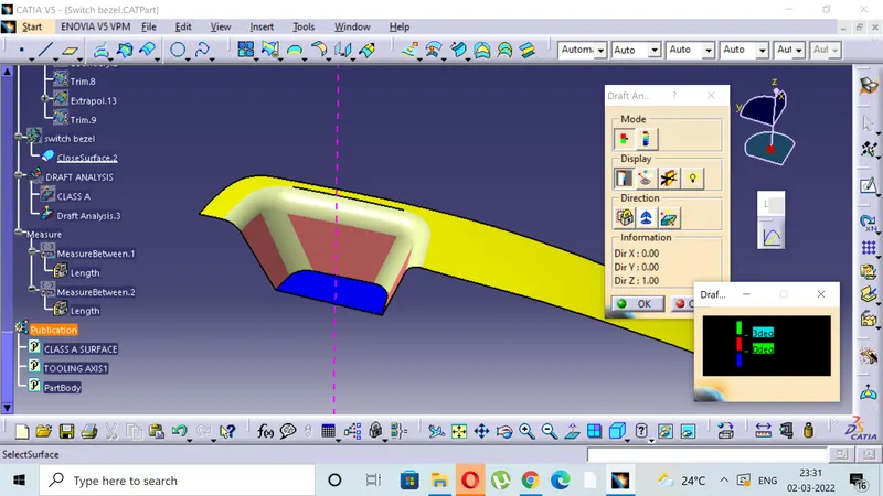
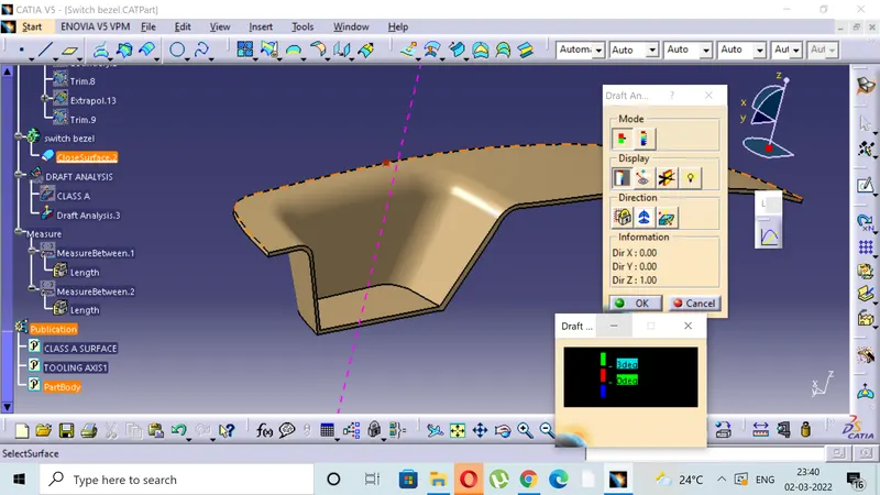
- MODES: The draft analyis toolbar provide two modes for analysis the draft , first is the quick analyis which basically has three colours for analyzing GREEN ,RED,AND BLUE on the other hand other option is the full analyis mode which enables few more detailing into the draft and is used in the complex components like instrument panel etc. In above challenge we have used the quick analysis mode for analysing draft here.
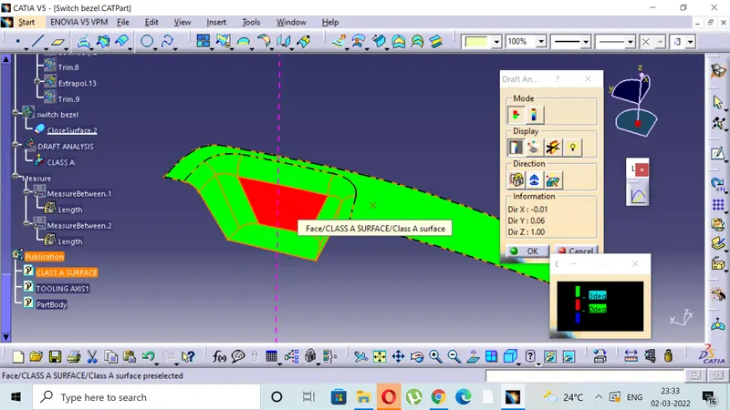
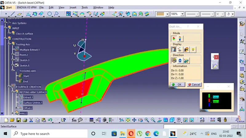
- After selecting the mode click on the compass in the direction section to set the compass aligned with the tooling axis and after the tooling axis and compass are aligned use the lock button to lock the compass movement.
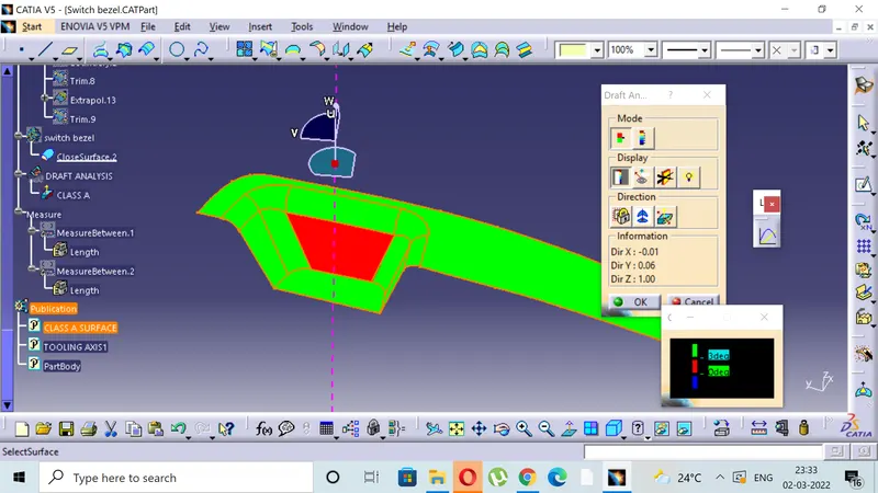
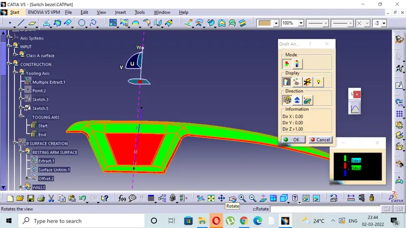
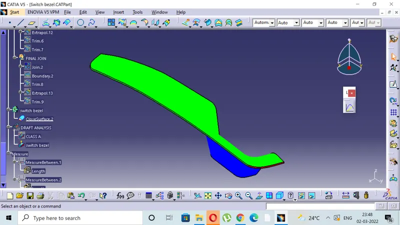
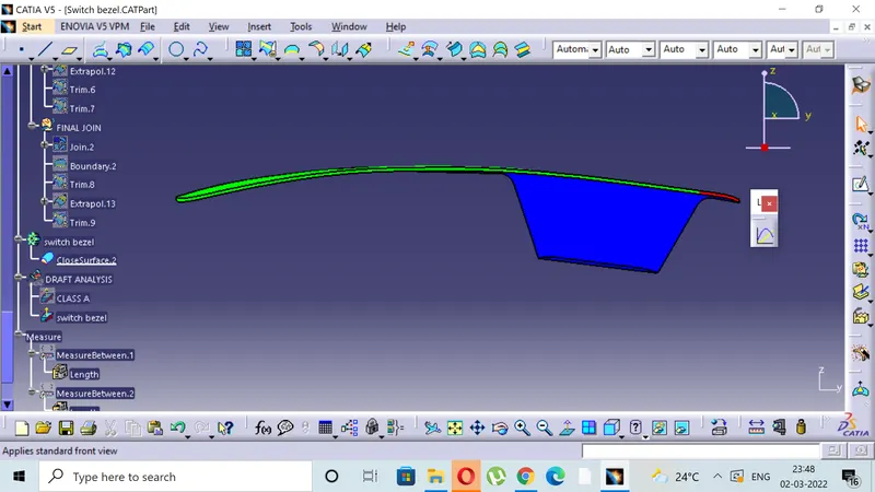
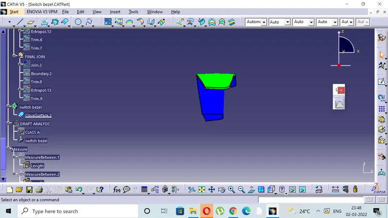
- After setting the compass along the tooling axis direction take the cursor on to the class A surface to analyze the surface, if the surface turns out be green fully it indicates draft value given is achieved throughout, we have given draft limit as 3 degrees minimum which is shown in colour code box (green colour), and blue colour indicates the negative draft.
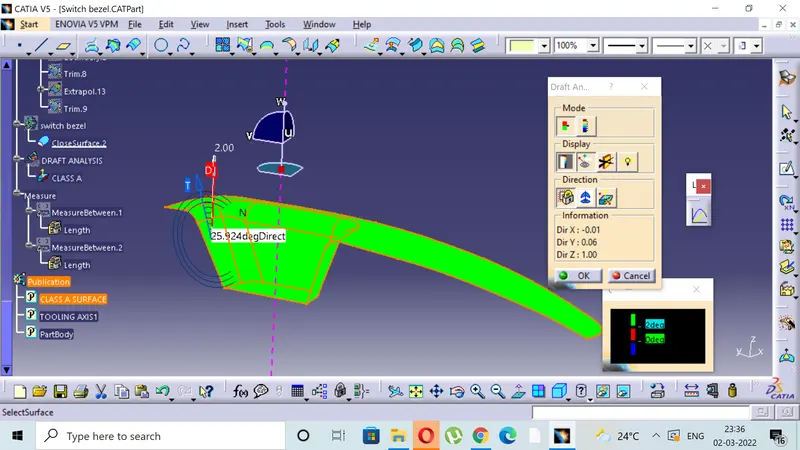
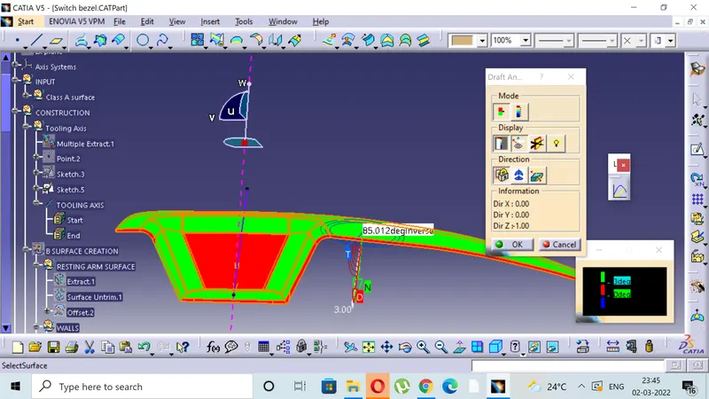
- To analyze the draft we have set minimum draft as 3 degrees .
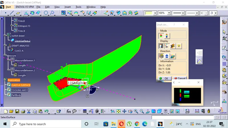
6) DRAFT IN VARIOUS VIEWS:
- ISOMETRIC VIEW
- FRONT VIEW
- LEFT SIDE
- RIGHT SIDE
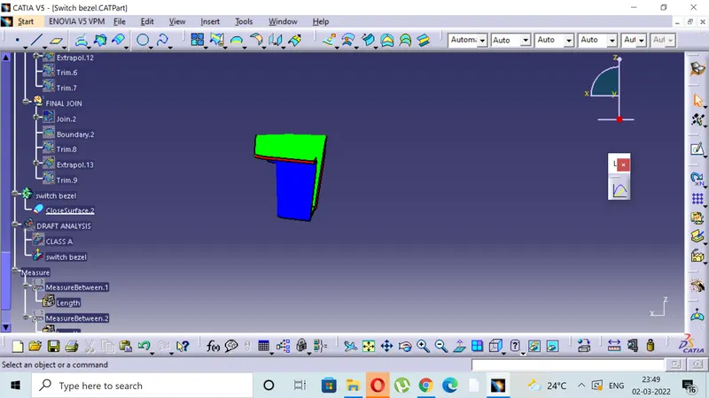
- TOP VIEW
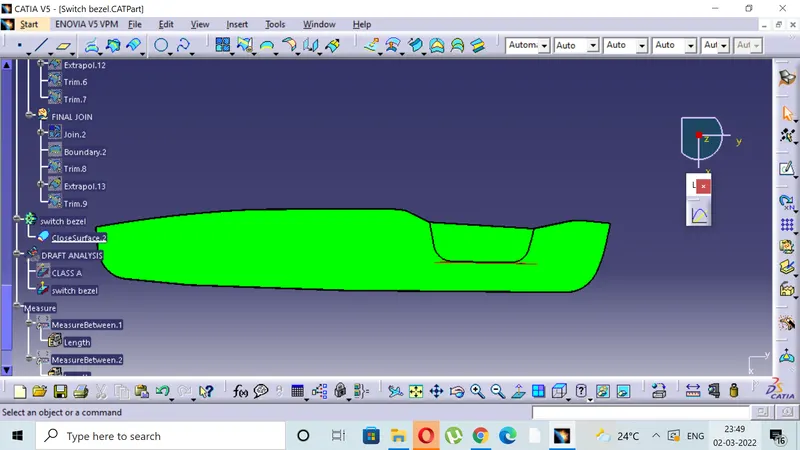
7) PUBLICATION CREATION.
After the creation of the tooling axis one should insert the publication from the insert tool. the publication serves your time while working on the class A for the draft analysis as well as thickening of the component. you can directly select your tooling axis and class A SURFACE as and when required during working on the class A surface .