Week 9 - Project - Master Section Development
Obejtive:
To design a B-Pillar from the provided Class-A surface and Master sections.
B-Pillar:
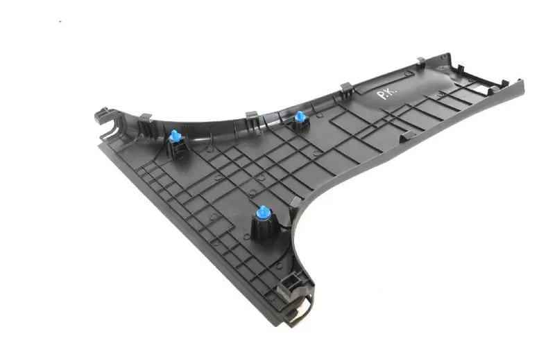
The B-Pillar Is The Central Pillar Of The Car. This Pillar Is Actually a Sheet Metal Part Which is Welded In The Biw Of The Car. The B-Pillar Trim Is Attached To The B-Pillar And improves The Aesthetic Look Of The Car. Mostly The Trims Are Manufactured By The Injection Molding Process. The Design Of The B-Pillar Is Carefully Done To Make The Part Manufacturable And Usable in The Interior. While Manufacturing a Part Through Injection Molding a Lot Of Defects Can Occur On The Plastic Part Which Will Destroy The Look Of The Panel. The Design Has To Made In Such a Way That All The Errors Can Be Rectified.
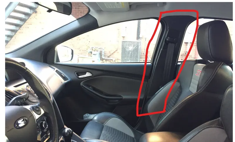
The Highligted region is the B-Pillar in a Car:
Procedure:
STEP-1:
1) Creation of TOOLING AXIS:
- To create tooling axis identify the correct axis, whether X,Y,Z axis is suitable for drawing.
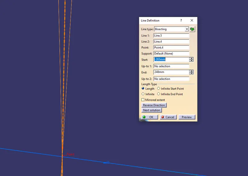
- Extract the lines from the master section, create a point inbetween the two extract lines.
- Draw a line along Y axis
- Draw a bisecting line the two points as reference.
Extract of lines from master-section
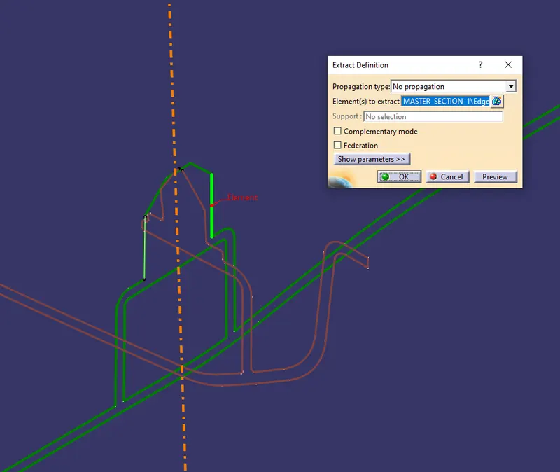
Bisecting Line to Create tooling axis
2) Creation of Flange for Class
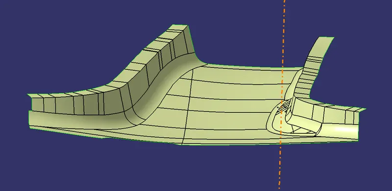
- The Flanges are created from the reference of the Master section.
- The flanges are created seperately and then trimmed with the class A surface.
- By taking intersection,Boundary and sweep.
- We shold create the sweep which is in the direction given in the master section.
Flange-1 & Flange-2 Creation:

Flanges Joined with the Main Body:
3) Class B Creation:
- The Class A body is offset to 2mm.
- The Flange-1 & Flange-2 is offset to 2mm.
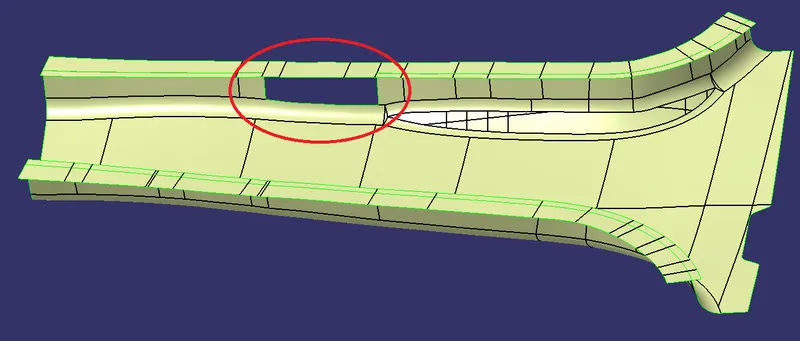
- Boundary is taken in Flange-2 as it is not getting trimmed.
- Extrapole is done on the boundary.
- Trim is used to remove the unwanted surface.
- The missing part is joined with spline and multi surface.
Missing Surface while offset of Class B:
Multisection used to fill the surface:
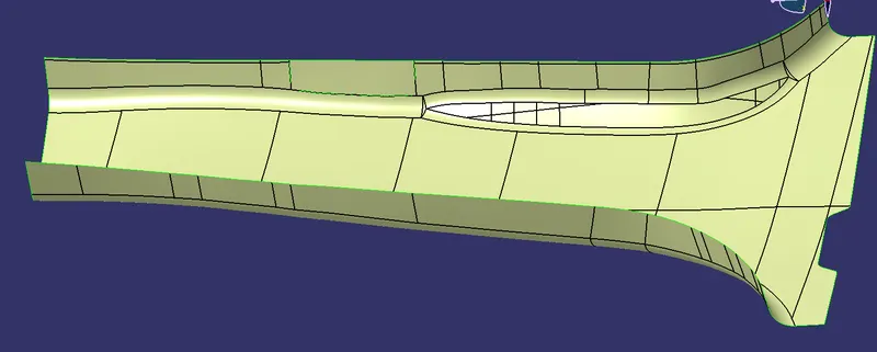
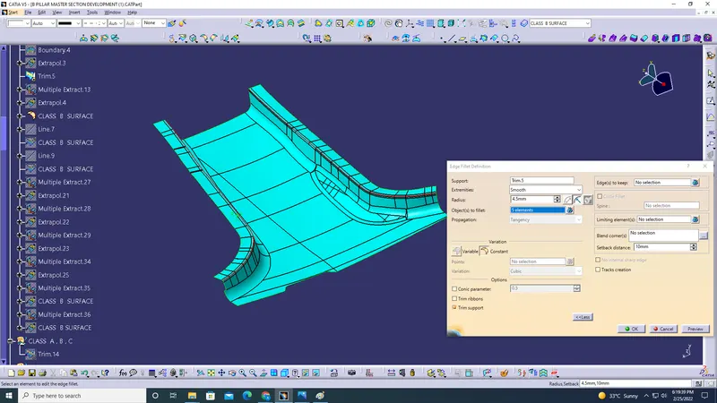
Edge Fillets given on the edges:
Creation of Class C Surface:
- The Class C surface is created by extracting the the edges of Class A.
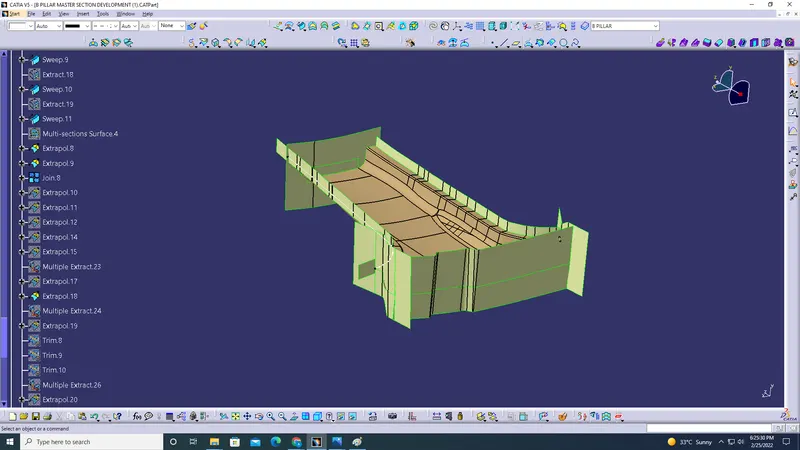
- Extrapole and sweep is used to create the C surface.
The below image shows the Class C surface created using sweep and extrapole:
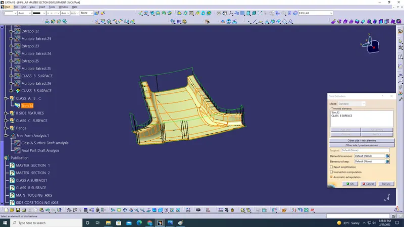
Creation of Class A+B+C created using Trim:
B-Side Featrures:
1) 4-way Locator:
1. From the master-section take the dimensions of the locator.
2. Pad it with appropriate thickness.
3. Give chamfer, draft and fillets according to the master section and design rules.
4. Use Boolean operation to join it to the model.
2) Ribs:
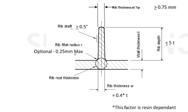
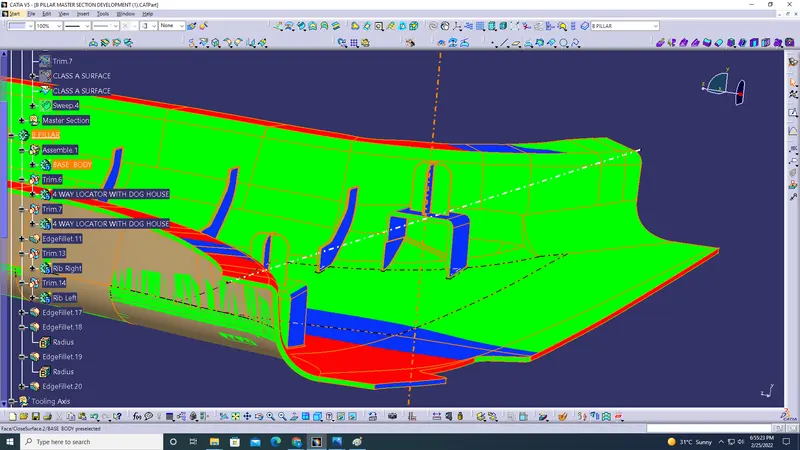
The only detail we have about ribs is that they are 50mm apart, so we make the ribs according to the design rules which are 50mm apart. They ribs should not be greater in height than flange. And also we will consider the height from the side wall according to the rules. Once that is done we will use Boolean operations to join it to the main body.
3) Dog House:
Using The Master Section The Doghouse Is Created And Then Part Modelled Using Thickness Option
-The 4 Way Locator Is Formed Above The Dog House Which Locates The B Pillar Towards The Mating Surfaces
-The Dog House Design Rules Are
-The Thickness Of The Connecting Surface Towards B Side Should Be 40% Off The Main Thickness
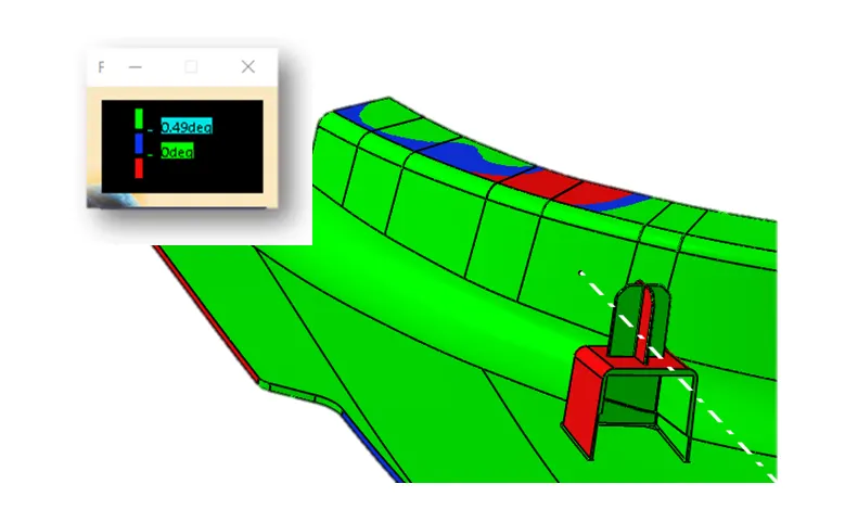
-The Walls Are Drafted With Min 0.5 Degrees Along The Main Tooling Direction
-The Attachement Feature Created Needs a Seperate Tooling Axis To Clear The Part Hence a Lifter Axis Is Used
-The Surfaces That Are Cleared Along The Lifter Axis Are Also Given a Minumal Draft
-The Height Of The Attahcment Walls Should Be a Minimum Of 3 Mm
-This Avoids The Plastic Defects On The B Side And Maintains The Texture Of A Side
Minimum Doghouse Width (X) for doghouses is 12 mm.
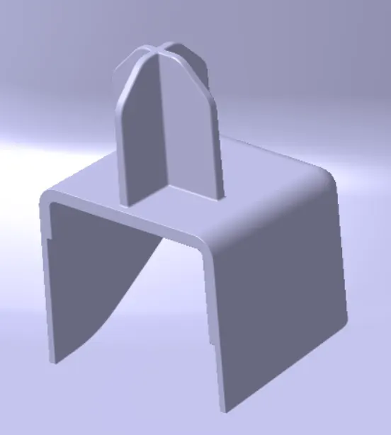
The BELOW PART WITH 4-WAY LOCATOR, Ribs and DOG HOUSE
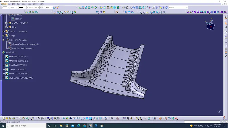
Draft Analysis:
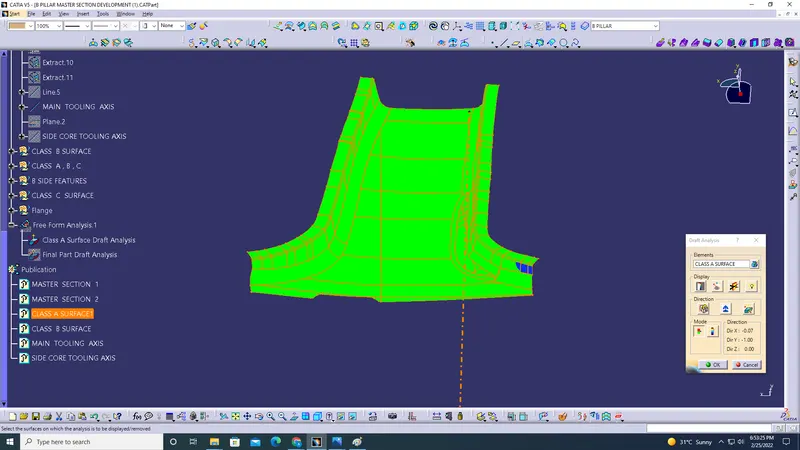
Draft on Class A surface:
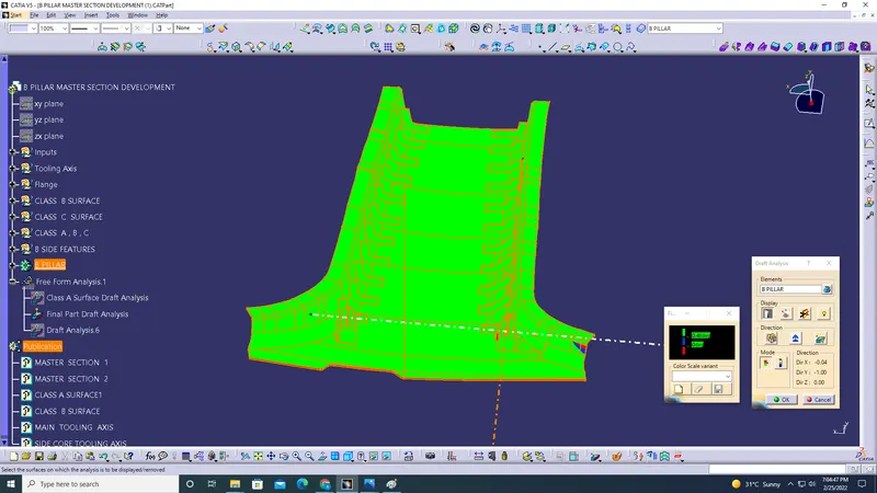
Final Part Draft:
Draft Analysis on Dog House:
Dog House Draft: