Week 9 - Project - Master Section Development
Report
B Pillar Design.
Introduction:
In this challenge we create a B pillar from the given class A surface and by following the design rules.
This project consists of three of the following parts:
- Draft analysis on the provided Class A surface of a B-Pillar.
- Create a solid model of the contour using Class B and Class C surfaces.
- Create B-side features such as ribs, locators and Doghouse.
Tooling axis of B Pillar:
- Tooling axis:
- The draft analysis is carried out by first creating a tooling axis.
- The tooling axis is created by taking intersection of the part features shown in the master section.
- The intersections are then used to create a bisecting line which is known as the tooling direction for that plane.
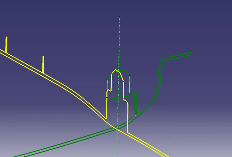
- – Tooling direction.
Draft analysis on the B Pillar:
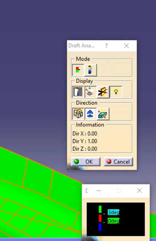
For the analysis, we input the tooling direction by placing the compass on the tooling axis and then selecting the part. The color gradient panel provides information about the draft angle based on the colors, with green colour being user defined while the red and blue colors are kept as 0 and negative respectively or else the user can define their own parameters for these colors.
Below are the images of the B Pillar analysis with the draft angle kept at 3 degrees.
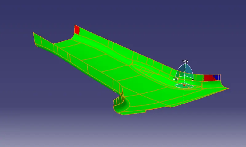
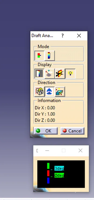
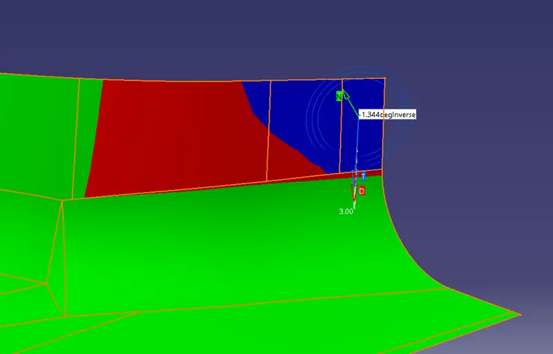
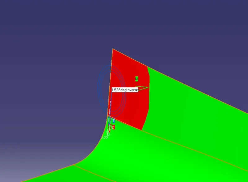
As seen in above images, the analysis shows zero or negative draft on some patches of the B Pillar wall surfaces as they do not have a draft angle with respect to the tooling axis.
Class B Surface:
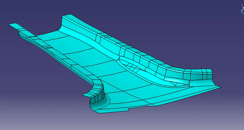
The class B surface is an offset of the class A surface with the offset distance being determined by the thickness of the actual part to be manufactured.
As Shown below, the highlighted surface is called the class B surface.
Class A and C surface:
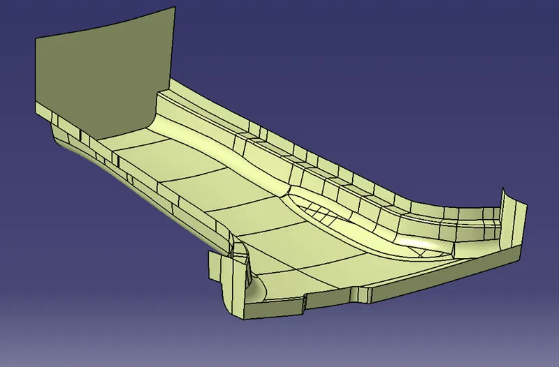
Class C surface is the perpendicular surface to the class A surface, it lies along the thickness of the part.
Surface C includes features like draft angle surface, hole surfaces etc.
As shown below the highlighted surface is the Class C surface.
Closed Surface:
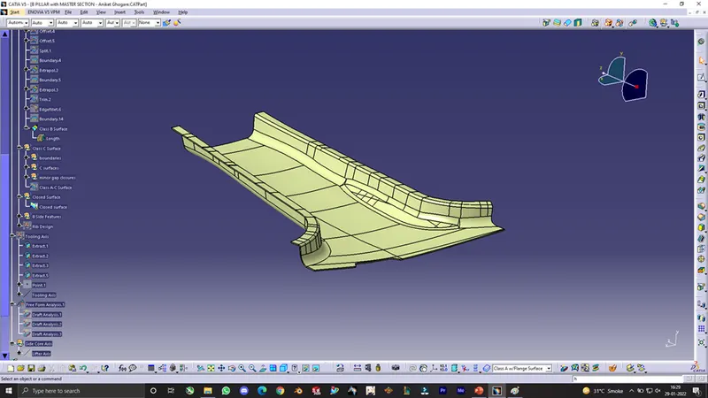
After creating the class B and class C surfaces, they are trimmed and joined with the parent Class A surface to create a closed surface of the part. The closed surface is then used to create the actual part body using solid features.
Shown below is the Closed Surface of the B Pillar design.
B Surface Features:
The b side features include the 4-way locators, ribs and doghouse.
- 4-way locators:
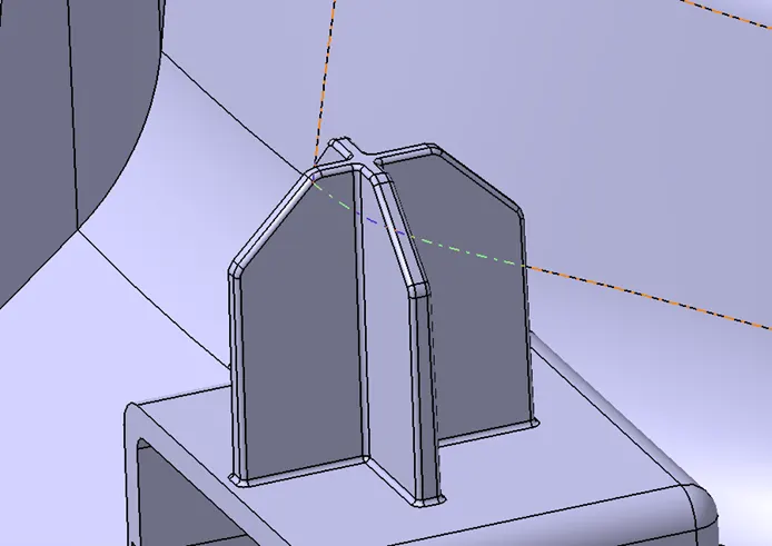
The 4-way locator is used for positioning a part while assembly processes.
These locators are created by first drawing its 2d sketch and then padding them in the tooling direction of the part.
The locators have a minimum 0.5-degree draft.
- Rib Design:
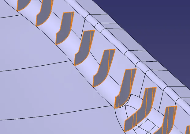
The ribs provide extra strength to a component. They are usually used when the part has a large flat section area without any bends.
The ribs are designed by creating 0.75mm plates at desired intervals and then trimmed with an offset of the class B surface to create the final rib contour as shown.
- Dog house Design:
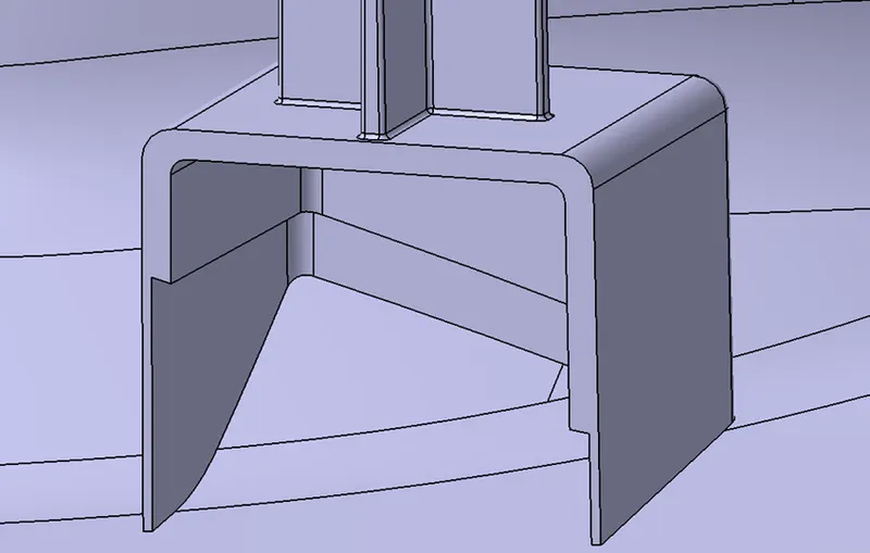
The dog house is used for avoiding sink marks on the main body surfaces. They are mainly sued when a b side feature has a larger wall thickness or length as compared to the main body, this can create undesirable sink marks on the class A surface. Hence doghouses are implemented as they have low wall thickness at its base that is in contact with the class B surface.
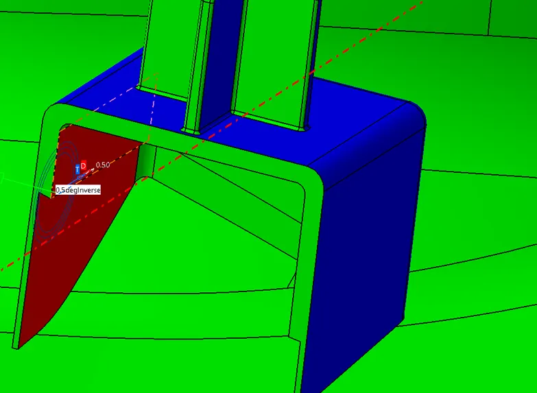
These doghouses have a 0.5 degree draft on its inner walls for proper side core action.
Solid Body:
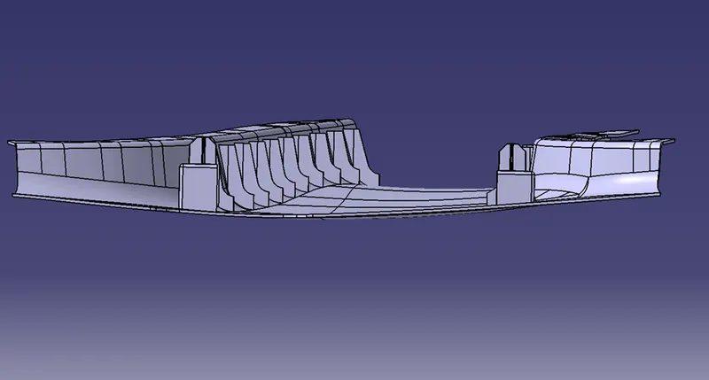
Solid Body can be created from the surfaces using various methos like closed body method or thicken surface method. The solid body represents the actual part body which will be manufactured.
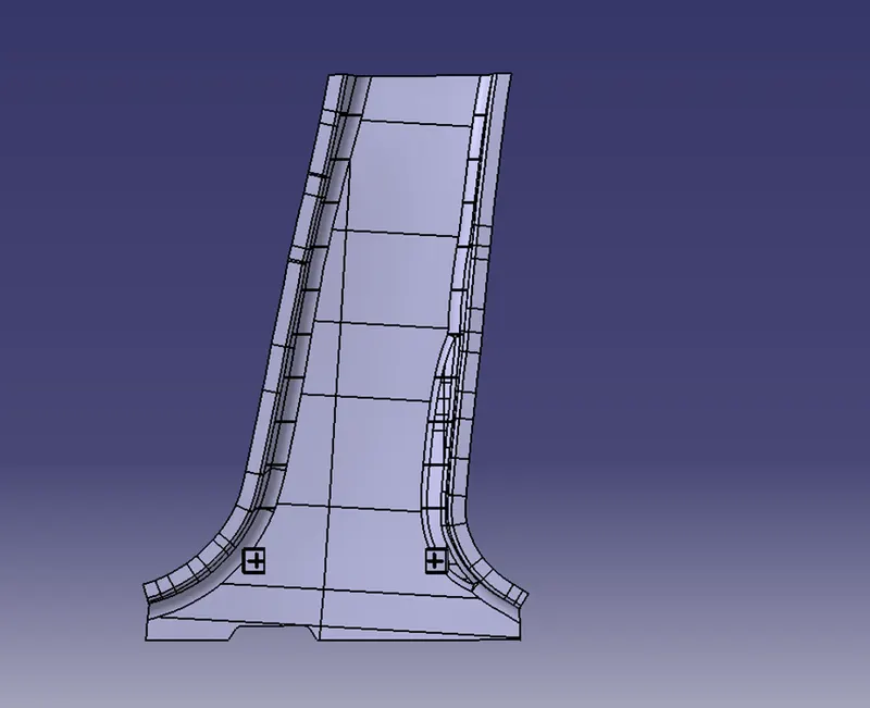
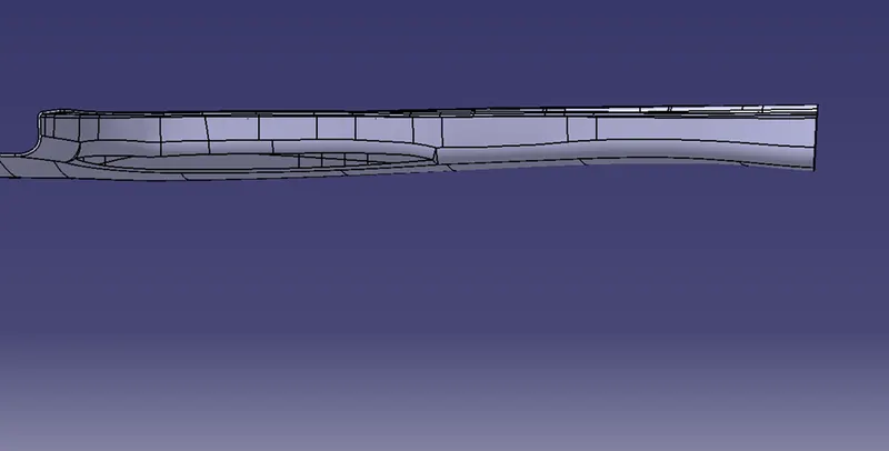
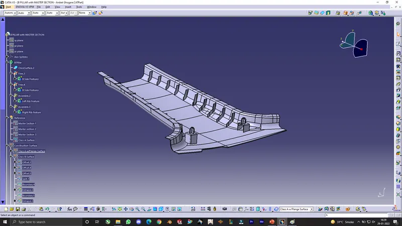
Shown below are some views of the Part body of the B Pillar.
- Front view:
- Top view:
- Side view:
- Isometric view:
Draft analysis on the Side core Axis:
- After creating the side tooling axis, we do a similar draft analysis on the side axis and check for any improper draft angles on the feature surface.
- As seen in the images, the draft angle on the side walls is 0.5 deg.
Conclusion:
- Thus after crating a solid body from the closed surface, we have designed the B pillar using surface modelling.
- We have also carried out draft analysis by creating suitable tooling directions for the part.