Radar Mast & Final Assembly of Yacht
Radar mast:
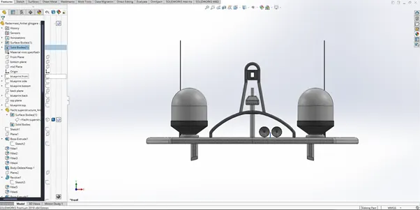
front view
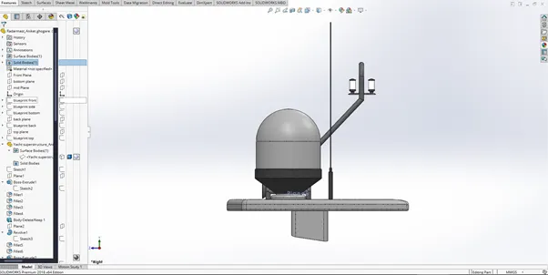
side view
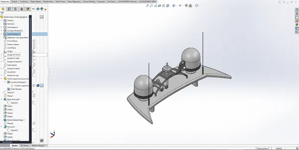
isometric view
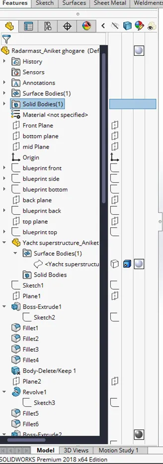
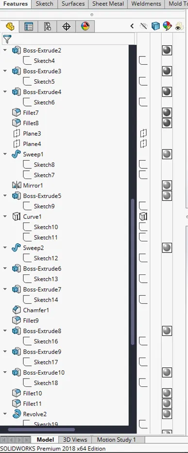
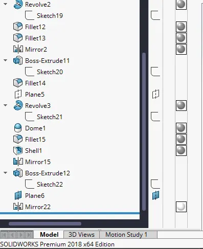
feature tree:
Assembly:
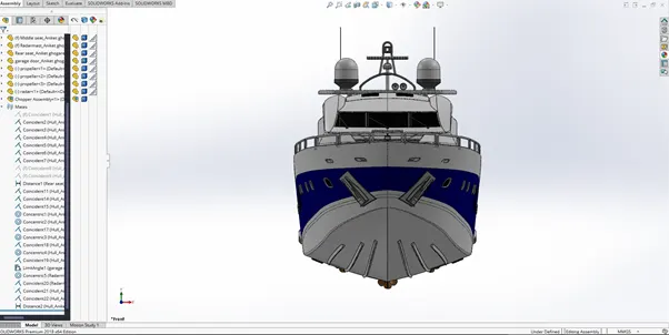
front view
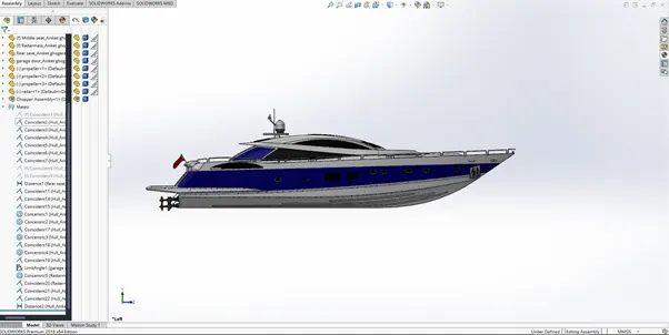
side view
isometric view
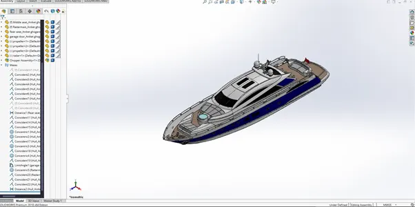
mates tree:
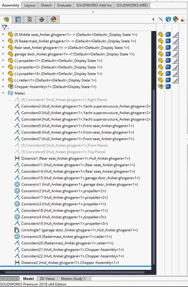
Report:
Modelling of Yacht
Objective:
To 3D model a predator yacht using solid-works.
Introduction:
In this project a full-scale model of Predator Yacht is created using solid-works in-order to understand and familiarize with different tools and methods for creating accurate 3D models.
Design Methodology:
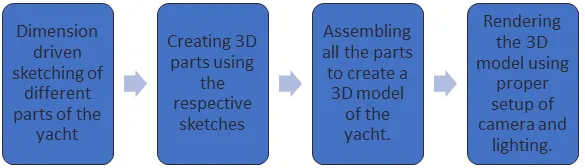
Description:
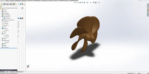
- Propeller:
A propeller consists of curved surfaces joined to an axle. To create these surfaces we use the loft tool which creates an extrude between two given sketches. The twist between these surfaces can be adjusted manually.
The axle is created by the revolve tool which revolves a sketch about a chosen axis of rotation.
To round off the edges of the profile a fillet of desired dimensions is applied.
The fillet tool rounds off sharp edges with a provided radius of curvature value.
The circular pattern tool creates a desired number of copies of the curved blade about the origin or about any selected circle.
- Radar:
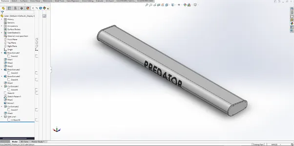
A Boss extrude of the provided sketch creates the base body of the radar as well as the side plates and the screws attached to these plates.
The screw sketch is copied using sketch driven pattern. In this tool a sketch is used for providing the location at which the patterned sketch is going to be copied.
To round off the edges of the profile a fillet of desired dimensions is applied.
The split line tool creates a separate surface using the chosen text projected on the front face of radar.
This surface can then be modified without disturbing the rest of the body.
- Hull:
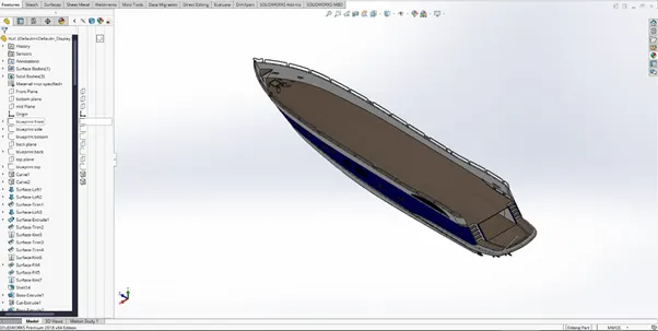
The hull is created by first modelling the surfaces and then converting them into a solid body before mirroring the entire body using the mirror entity tool.
Most of the curves are created using projected curve tool which takes two sketches and creates a separate curve along the intersection plane of the first two sketches.
To create the different surfaces, surface loft and surface extrude is used.
A surface loft uses open sketches or curves to create a surface along a chosen guide sketch/curve.
A surface extrude only creates a straight surface along a chosen direction.
The surfaces are merged together using knit surface which combines different surfaces and patches any gaps in-between these surfaces using the gap control option.
The railing as well as the window frames are created by using swept boss tool which creates a solid extrude along a curve sketch which can be either open or closed.
The propeller mountings are created using revolve tool. The sketch is revolved along its centre axis to create the mounting which is then linearly patterned along a single line sketch.
To round off the edges a fillet of desired radius is used. Also a chamfer is given to these edges.
The chamfer is of distance – distance type.
Once the surfaces are merged into a solid body, a shell tool is used to hollow out the entire body.
The shell tool creates a hollow body with manually provided wall thickness values.
As the body is to be mirrored, the middle section is to be completely removed which is an option in shell tool to select surfaces which are to be completely removed.
The stairs section is created using extrude cut with their respective sketches.
The garage space is separated from the body using cut extrude and then saved externally as a separate part.
An offset surface tool is used to create a copy of deck surface. We give a 0mm offset in the offset tool to create a reference body for other parts.
Finally the body is mirrored along mid-plane using mirror entities tool. The merge entities option combines the mirrored body and the original into one body.
- Front seat:
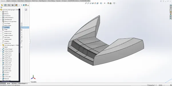
For the reference, we import an external part (hull) and select only the surface bodies option to create the deck surface as reference for the seat.
The base structure is created using surface sweep and surface extrude.
The unwanted parts of these surfaces are removed using surface-trim tool.
The surface trim tool takes a selected surface as the base for trimming other surfaces that intersect it. We can choose the keep selections or remove selections option based on the selections.
The surfaces are knit together using knit tool to merge them and create a solid body.
The seats are created by using offset surface tool.
The offset surface tool creates an identical surface at a distance. This surface is then extruded to create a solid body for the base seat structure.
This structure is then separated using cut extrude of a sketch.
To create the curvature on the seats surface, dome tool is used.
Dome tool curves a flat surface into a circular or elliptical manner by manually providing the radius values.
The mirror tool copies the entire body along the selected plane (mid plane in this case).
To round off the edges of the profile a fillet of desired dimensions is applied.
- Middle seat:
For the reference, we import an external part (hull) and select only the surface bodies option to create the deck surface as reference for the seat.
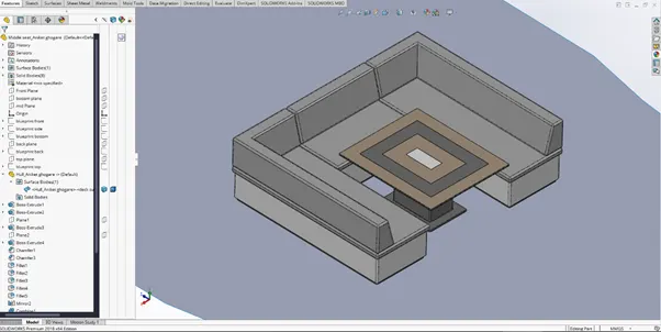
Boss extrude is used to create the base structure, the seats, the supports, and the table.
A inclined shape of seats is created by the chamfer tool of distance-distance type.
This chamfer method allows user to define the vertical and horizontal distances manually for the material removal.
The seats and the base body are mirrored along the selected plane using mirror entities tool.
The table-top design is created using cut extrude of closed sketch.
In this case the contours of sketch are to be manually selected for the cut extrude.
Finally to round off the edges of the profile a fillet of desired dimensions is applied.
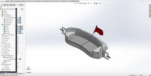
- Rear seat:
For the reference, we import an external part (hull) and select only the surface bodies option to create the deck surface as reference for the seat.
The rear seat is created similarly to the front seat that is using surfaces to create a final solid body.
For creating the base structure various tools are used, such as:
Surface extrude:
Creates a straight surface from an open sketch.
Surface loft:
Creates a surface between two open curves or sketches whose curvature is based on a sketch intersecting both the selected curves/sketches.
Surface trim:
Trims a surface based on another surface or an open sketch. The part to be removed from the surface can be manually selected.
Surface extend:
Extends a selected surface from a selected edge while maintaining its curvature.
Surface sweep:
Creates a surface from an open profile sketch along a guide sketch/curve.
The surfaces are merged into a solid body using knit surface to remove any gaps in the geometry using gap control option.
To create the seats, the offset surface tool is used to create a separate surface.
This surface is then extruded into solid body using boss extrude.
Cut extrude creates the holes for the cup holder and the door supports.
The side gates are created using sweep tool which sweeps a circular profile along the sketch.
The bottom part of the gate is then mirrored to create the complete structure of the gate.
The entire body is then mirrored along the selected plane and merged using the mirror entities tool.
For the flag, we use a revolve tool to create the flag pole.
For the flag cloth, a 3D sketch of splines is used.
The loft surface tool creates the flag surface using these 3D sketches.
- Superstructure:
For the reference, we import an external part (hull) and select only the surface bodies option to create the deck surface as reference for the seat.
The 3D curves are created using project curve tool.
For creating the base structure various tools are used, such as:
Surface extrude:
Creates a straight surface from an open sketch.
Surface loft:
Creates a surface between two open curves or sketches whose curvature is based on a sketch intersecting both the selected curves/sketches.
Surface trim:
Trims a surface based on another surface or an open sketch. The part to be removed from the surface can be manually selected.
Surface extend:
Extends a selected surface from a selected edge while maintaining its curvature.
Surface sweep:
Creates a surface from an open profile sketch along a guide sketch/curve.
Ruled surface:
Creates a surface up-to a specified distance originating from the selected edges of the base surface.
Surface fill:
Creates a filled surface between the boundaries of other surfaces/curves/sketches. The boundary must be a closed boundary formed by selected edges.
The surfaces are merged into a single surface body using knit surface to remove any gaps in the geometry using gap control option.
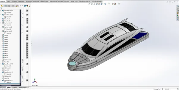
A fillet of desired radius is given to certain edges of the body.
For the windows , cut extrude of specified distance is used. Cut extrude is done by offset from surface method which projects the selected sketch contour onto the selected surface for offset.
The direction of offset selected manually by user.
The window frames are created by boss extrude using a similar offset from surface option.
We use sweep surface and chamfer tool for creating the window wipers.
The jacuzzi seats are created similarly to the front and rear seats of yacht.
The jacuzzi is created using boss extrude of circular profile.
The excess part of jacuzzi is removed using cut extrude tool.
The solid body of jacuzzi is converted to surface body by delete faces tool which deletes the selected face from the body creating an open hollow body.
The entire body is converted to a solid body by using knit surfaces again but selecting the create solid body option this time.
The solid body is then mirrored along selected plane using mirror entities tool.
One of the surfaces of roof is offset using offset entities tool.
A split line tool is used to create a separate surfaces on the base surface which can be used for reference in radar-mast part.
- Radar-mast:
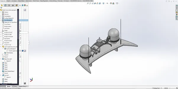
A boss extrude is used to create the base structure of the mast, the antennas and the support stands.
A revolve boss tool is used to create the circular components as well as the horns.
The ladder structure is created using a sweep tool.
This sweep is mirrored about a reference plane to create the second side of the ladder.
A boss extrude with midplane option is used to create the centre rods of the ladder.
Fillet tool is used to round off the edges if the entire body.
A mirror tool is used to create the other half of the body and combine it into one single body using the merge body option.
- Assembly:
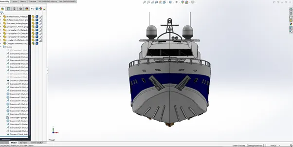
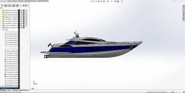
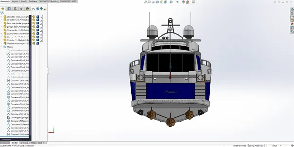
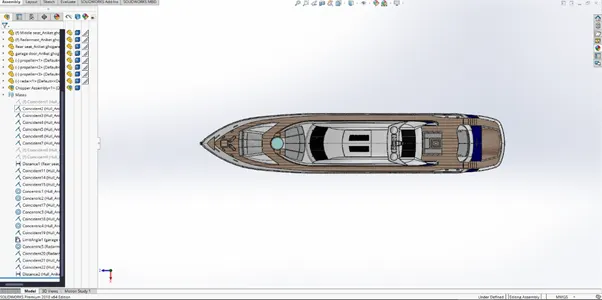
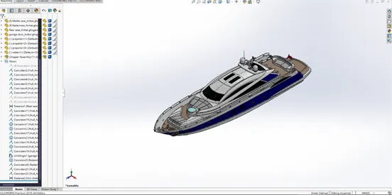
To assemble the different parts, we import them one by one and apply appropriate mates to constrain them in the right place on the assembly.
The hull is used as the base part and fixed in the assembly.
As the parts were created using reference surfaces from the hull and the superstructure respectively, they get constrained automatically into place without manual input.
Some parts such as garage door, radar and propeller are to be constrained manually.
Assembly views:
Front view:
Side view:
Back view:
Top view:
Isometric view:
- Rendering:
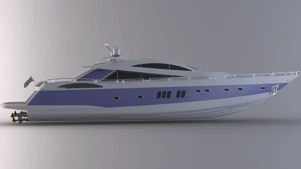
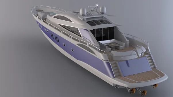
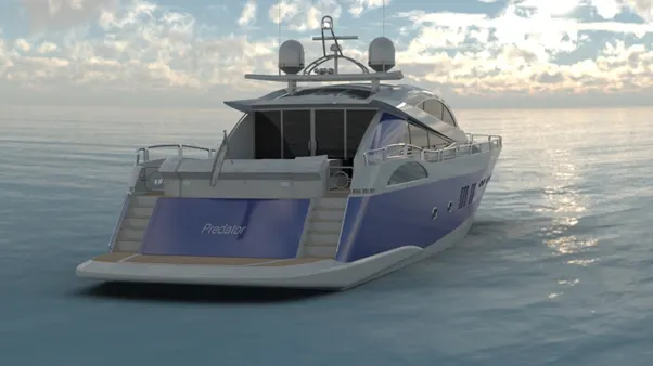
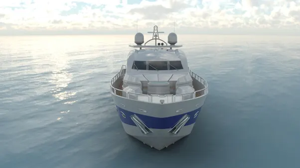
After applying desired materials to the body and setting up the cameras we can render the final model in visualize or photoview 360.
Below are some rendered images of the yacht.
Conclusion:
With the above mentioned steps, the detailed modelling and rendering of the predator yacht is completed.