Photo Realistic Rendering
American Chopper
Objective:
To create a detailed model of the American chopper using solid-works.
Introduction:
In this project a full-scale model of American chopper is created using solid-works in-order to understand and familiarize with different tools and methods for creating accurate 3D models.
Design Methodology:
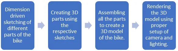
Description:
- Transmission Belt:
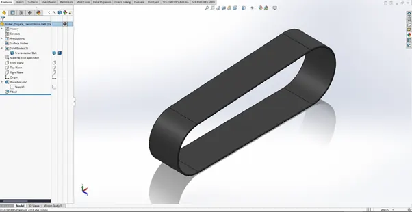
After drawing a fully defined sketch we use extrude boss to create a 3D profile of the sketch.
To round off the edges of the profile a fillet of desired dimensions is applied.
- Kickstand:
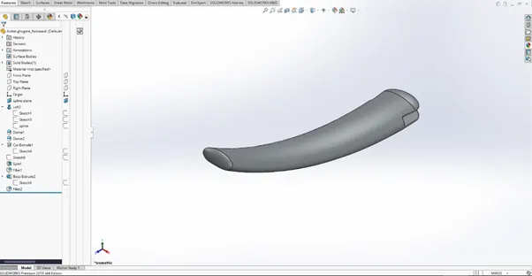
A loft tool is used to create a curved profile between two ellipses using a spline as its path.
A dome tool is used to round off the top and bottom part of kickstand.
To create the slot at the top of the stand, an extruded cut of a rectangle is used.
An extrude boss of a circular sketch is used to create a lock to mount the kickstand on the chassis.
- Front fender:
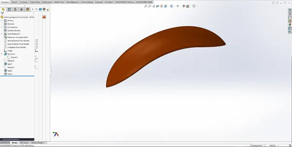
A revolve tool is used to create the arc of the fender about the origin.
To create the top and bottom shape of the fender, a split tool is used to cut the 3D profile along the respective sketches to cut the top and bottom part of the arc.
A fillet of desired radius is used to round off the edges.
- Rear fender:
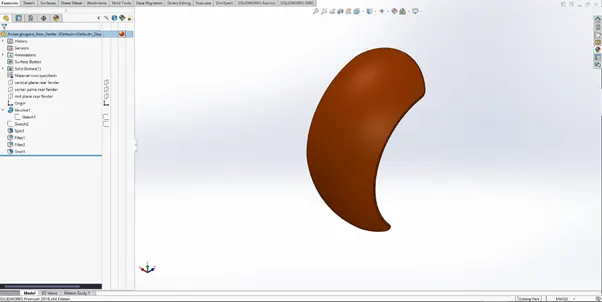
A revolve tool is used to create the arc of the fender about the origin.
To create the top and bottom shape of the fender, a split tool is used to cut the 3D profile along the respective sketches to cut the top and bottom part of the arc.
A fillet of desired radius is used to round off the edges.
The shell tool is used to create a hollow shell from the 3d profile by removing a desired amount of material.
- Pedal:
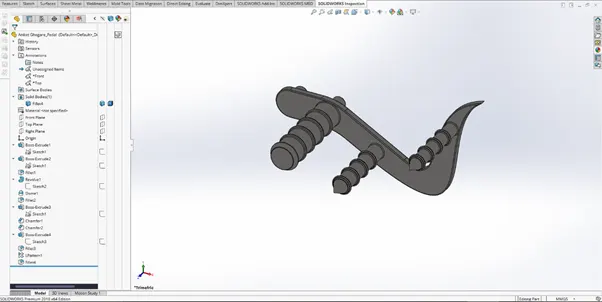
An extrude boss is used to create the structure plate as well as the circular supports on both sides.
For the main foot support a revolve of its sketch is used. To round off its end a dome tool with desired radius is used.
For the conical ends on other two supports, a chamfer of distance-angle is used.
For the circular design, a linear pattern of its boss extrude is used.
A fillet of desired radius is used to round off the edges.
- Chain-link:
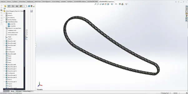
The sketch of inner and outer plate of chain-link is converted into blocks and saved externally at the desired location.
A boss extrude of the sketch block and the sketch of pins is used to create a single chain-link piece.
To create the rest of the link a circular pattern tool is used to create the complete chain-link along the sketched curved path.
All the inner and outer plates along with the pins are segregated into their respective folders to make it easy for applying different appereances.
- Chassis:
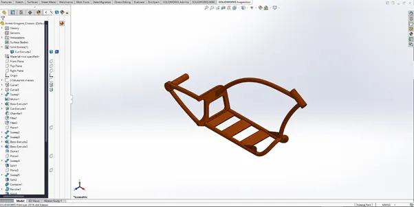
In order to create the chassis a blueprint of the entire bike is used by sketch picture tool which imports external images into the sketch plane for reference.
For creating the curved profiles a sweep of a sketch along the projected curves is made using sweep tool.
Boss extrude is used for creating the support plates as well as the rear wheel mounting.
A cut extrude is used for removing the material from back frame as well as for creating a mounting space for the pedal on both sides.
A fillet of desired radius is used to round off the edges.
A split tool is used to remove excess material from inside the front fork mounting.
- Front wheel:
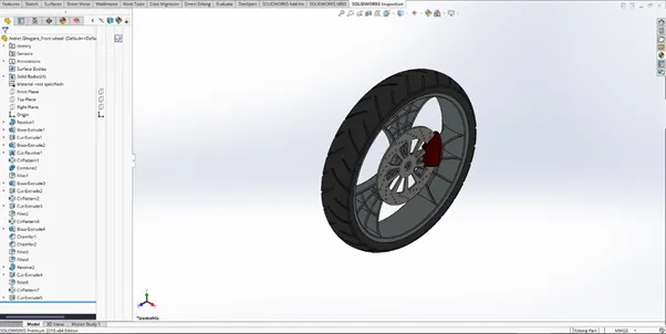
The revolve tool is used for creating the rim as well as the tyre.
A boss extrude of the rim design as well as the axle is created from its respective sketches.
Cut extrude tool is used to remove excess material from the rim design as well as the axle.
A linear pattern tool is used to pattern the rim design around the axle at equal spacing.
To create the disc brake, a boss extrude of the disc sketch is made.
A cut extrude of linear patterned sketch of circular holes as well as the sketch of compound shape is made.
The cut extrude of these two sketches is used in a circular pattern to remove material from the entire disc.
A boss extrude of the calliper sketch is created. For its edges, a chamfer with distance-distance method is used.
A linear pattern of offset cut extrude is sued to create the pattern on the tyre.
A fillet of desired radius is used to round off the edges.
- Rear wheel:
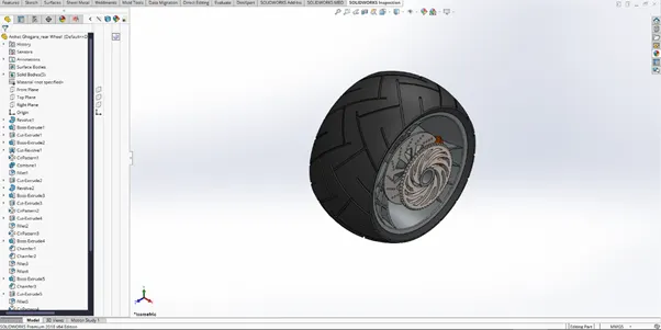
The revolve tool is used for creating the rim as well as the tyre.
A boss extrude of the rim design as well as the axle is created from its respective sketches.
Cut extrude tool is used to remove excess material from the rim design as well as the axle.
A revolve tool is used to create the pointed end of the the axle.
A linear pattern tool is used to pattern the rim design around the axle at equal spacing.
To create the disc brake, a boss extrude of the disc sketch is made.
A cut extrude of linear patterned sketch of circular holes as well as the sketch of compound shape is made.
The cut extrude of these two sketches is used in a circular pattern to remove material from the entire disc.
A boss extrude of the calliper sketch is created. For its edges, a chamfer with distance-distance method is used.
For the sprocket a boss extrude of its sketch is created.
A cut extrude of compound shape is made. This cut extrude is used in a circular pattern to remove material from the entire sprocket as well as to create the mounting for the chain-link.
A linear pattern of offset cut extrude is sued to create the pattern on the tyre.
A fillet of desired radius is used to round off the edges.
- Front fork:
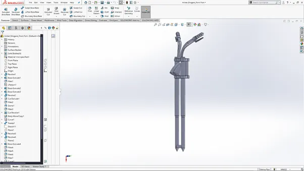
A revolve tool is used to create a single fork.
A linear pattern of boss extruded plates is used to create the top and bottom plates.
An offset revolve of headlight sketch is used to create a single headlight profile.
A dome tool is used to give the convex shape to create a realistic glass for the headlight. A chamfer tool is used to give detail to the glass .
A boss extrude is used to create the front axle as well as the chassis mounting.
A sweep tool is used to create the handle profile as well as the brake-wires using projected curves.
A revolve tool is used to create the handle grip.
For the brakes, a boss extrude of a sketch created on referenced plane is used.
A fillet of desired radius is used to round off the edges.
The mirror tool is used to create the other side of front fork.
A combine tool is used to combine both the sides of front fork.
- Engine:
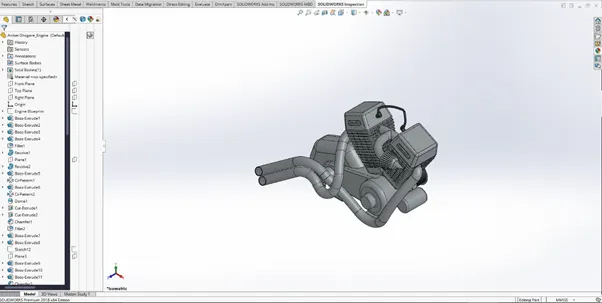
The boss extrude and revolve is used to create the base profile of engine as well as the bottom supports.
A reference geometry tool is used to cerate appropriate planes for sketching the geometry of engine.
A linear pattern tool is used to create the fins on cylinder.
A dome tool is used to create the details on the cylinder.
The cylinder is mirrored using mirror tool to create the second identical cylinder.
A composite curve is created using different projected curves to create a sweep of the exhaust.
The air intake pipe is created using sweep along the respective sketch.
A revolve is sued to create the air filter. The circular pattern of boss extrude is used to create the detailed cuts on the filter.
A fillet and chamfer of desired radius or distance is used to round off the edges.
- Gas tank:
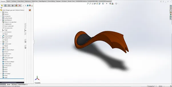
A surface sweep is used to create a single side of the upper face of the tank.
A surface trim tool is used to remove excess material from the face.
A projected curve tool is used to create the side curves for the tank. These curves are used in surface loft and boundary surface tool to create the side face of the tank.
The side face as well as the top face is mirrored using mirror tool to create the other half of the tank.
The faces are merged together using knit surface tool.
Split line tool is used to create the surface for seat.
A surface extrude is used to create the seat profile.
The bottom surface is created using surface loft between the two side faces.
The merged surfaces are converted into solid body.
The spacing for chassis is created using cut sweep tool along a curved path.
Lastly a shell tool is used to hollow out the tank upto desired thickness.
A fillet of desired radius is used to round off the edges.
- Oil tank:
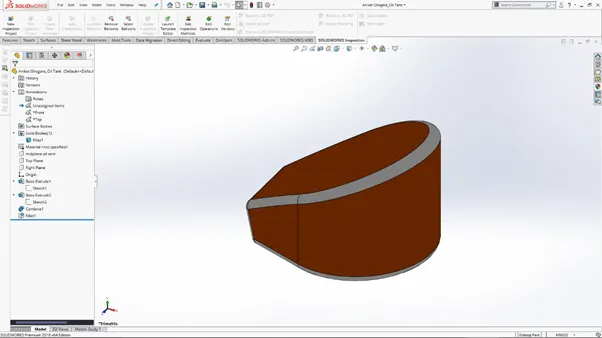
A boss extrude of two sketches is used to create a base profile for the tank.
A combine tool is used to merge the two profiles and only keep the common parts by opting for the common operation method.
A fillet of desired radius is used to round off the edges.
- Assembly:
With the insert components tool insert various parts of the bike in an order to assemble the complete bike.
The mates tool is used to constrain the parts in their respective place.
With appropriate constraints, the entire bike is assembled.
From the feature tree manager desired appearances can be given to various parts.
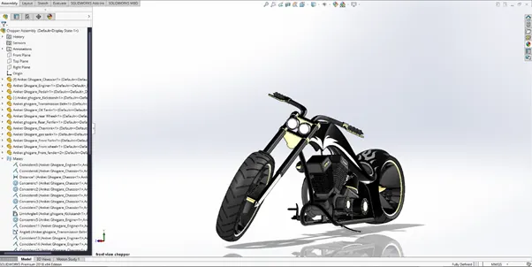
Assembly camera setup view.
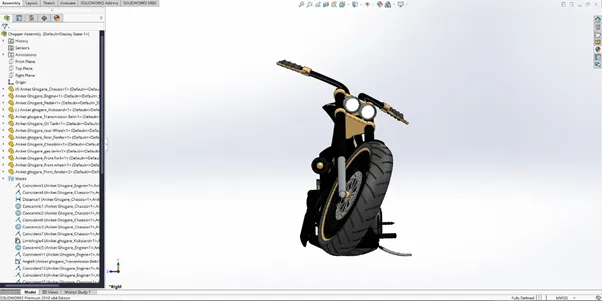
Assembly front view.
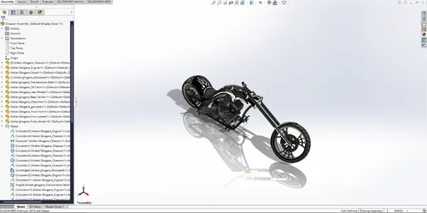
Assembly isometric view.
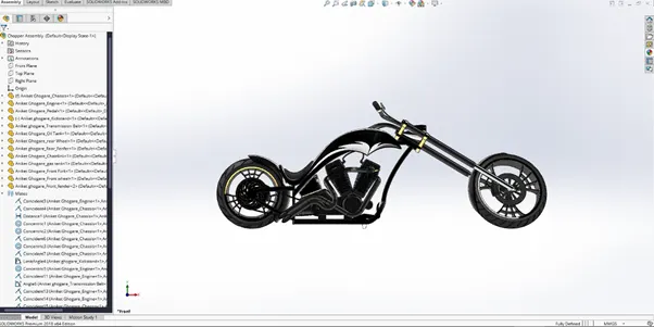
Assembly side view.
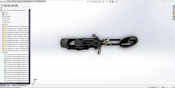
Assembly top view.
- Rendering:
With proper camera setup and lighting environment, the assembly is rendered for a realistic view. (Rendering done in solidworks visualize)
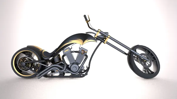
Side View.
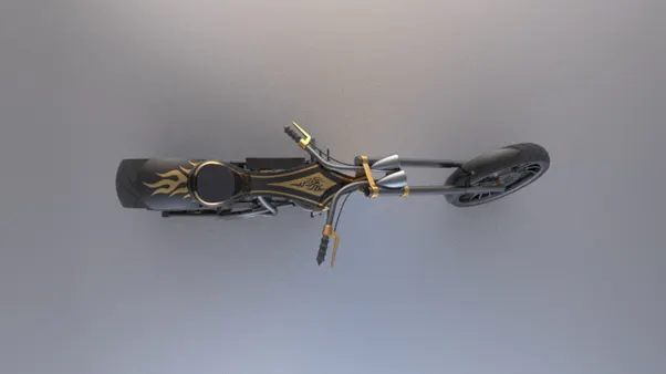
Top view.
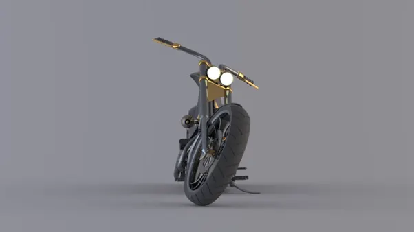
Front view.
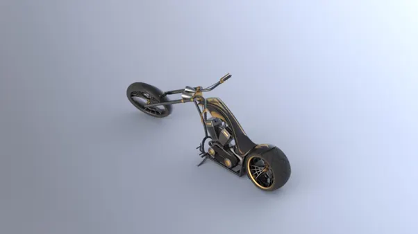
Isometric view.
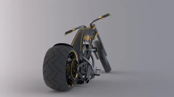
Camera setup view 1.
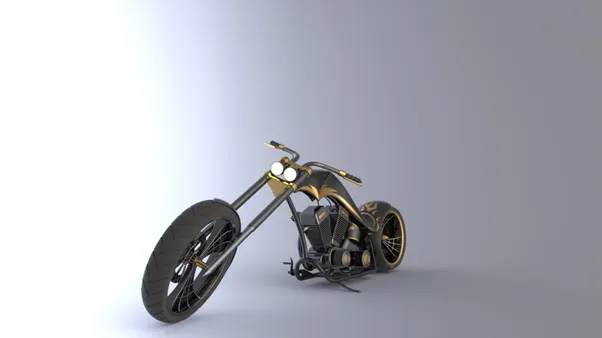
Camera setup view 2.
Conclusion:
By following the briefly mentioned steps, the complete assembly and Rendering of American chopper is completed in solidworks.